Chapter 1: Introduction to Petroleum Engineering and the E&P Industry#
Learning Objectives#
By the end of this chapter, you will be able to:
Describe where petroleum engineering fits within the broader energy sector
Explain the origin of hydrocarbons and the geological conditions required for their accumulation
Identify the three segments of the oil and gas industry (upstream, midstream, downstream) and the activities within each
Outline the phases of an exploration and production project, from initial exploration through abandonment
Explain the role of the drilling engineer within the E&P process
Discuss how drilling technology applies beyond oil and gas, including geothermal energy
1.1 What is Petroleum Engineering?#
Petroleum engineering is the branch of engineering concerned with the exploration, development, and production of oil and natural gas. It draws on geology, physics, chemistry, and classical engineering disciplines to solve problems that range from finding hydrocarbons deep underground to delivering them safely to the surface and into the supply chain.
As a field, petroleum engineering sits at the intersection of the physical sciences and practical field operations. Calculations that seem abstract in a classroom — fluid pressures, pipe mechanics, heat transfer — directly control whether a well succeeds or fails, and whether it does so safely. A misplaced decimal point in a pressure calculation is not just an academic error; in the field it can cause equipment failure or a well blowout. This is one reason why petroleum engineering courses emphasize both getting the right answer and using the right procedure.
The discipline encompasses several specializations:
Drilling engineering — designing and executing the process of boring a wellbore from surface to the target reservoir
Reservoir engineering — characterizing the subsurface rock and fluid system, developing a model of the reservoir, and forecasting production
Production engineering — optimizing the flow of hydrocarbons from reservoir to surface facilities
Completions engineering — designing the interface between the wellbore and the reservoir (e.g., casing, perforations, hydraulic fracturing)
This textbook focuses on drilling engineering, which is in many ways the first step in any oil and gas — or geothermal — project. Without a well, there is nothing to produce.
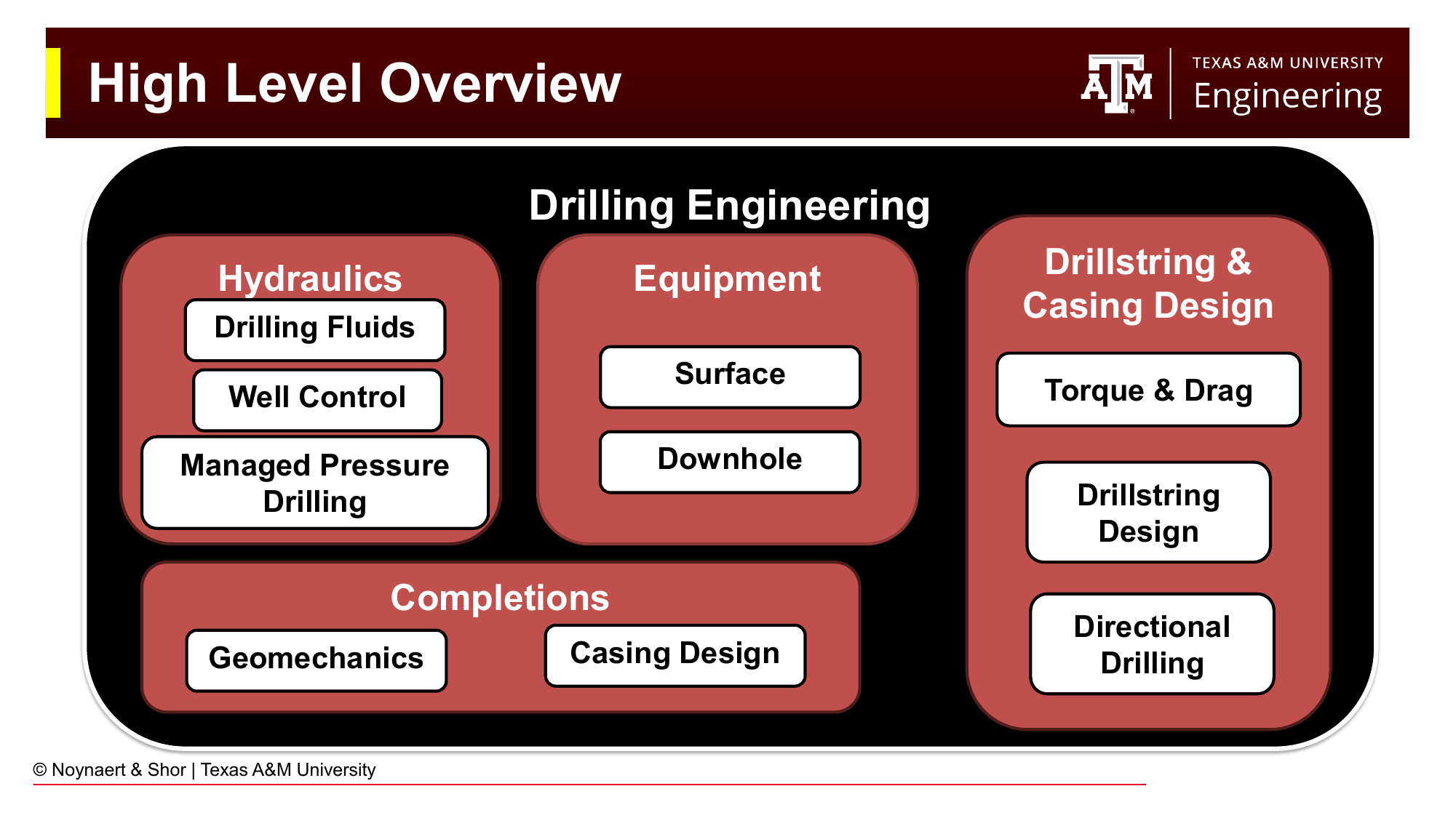
Fig. 1 High-level overview of drilling engineering, showing the major technical areas that make up the discipline. Topics covered in this textbook are highlighted.#
1.2 Why Hydrocarbons? The Energy Density Argument#
Before diving into how we find and extract hydrocarbons, it is worth asking: why are they so valuable as an energy source?
The answer is largely energy density. A single US gallon of gasoline weighs roughly 6 pounds (2.7 kg) and can propel a typical car 30–50 miles. Equivalently for the Europeans, it takes between 2 and 10 litres to propel the same car 100 km. To store the equivalent energy electrochemically in a lithium-ion battery requires roughly 300 pounds (140 kg) of battery pack — about fifty times the mass (see Problem 1.5). Hydrocarbons pack an enormous amount of chemical energy into a small, stable, easily transported volume. They are also liquid at standard conditions, making storage and distribution straightforward compared to gases or solids. The same battery can be recharged hundreds to thousands of times, but still require significant materials and energy to manufacture and recycle, and are still relatively slow at charging (20-40 minutes to fast charge a battery compared with 1-5 minutes to fill up a fuel tank).
This energy density advantage, combined with over a century of infrastructure development, is why petroleum remains a dominant global energy source even as renewable energy expands rapidly. Understanding this context helps frame why the petroleum industry invests billions of dollars annually to find and access hydrocarbon deposits kilometers underground.
1.3 Where Do Hydrocarbons Come From?#
1.3.1 Rock Types and Sedimentary Basins#
The Earth’s crust is composed of three broad categories of rock:
Igneous rocks form from the cooling and solidification of magma (e.g., granite, basalt)
Metamorphic rocks form when existing rocks are subjected to high heat and pressure without melting (e.g., marble, schist)
Sedimentary rocks form from the accumulation and compaction of sediment particles over geological time (e.g., sandstone, shale, limestone)
Oil and gas are found almost exclusively in sedimentary rocks. Sedimentary basins — large depressions where sediments accumulate over millions of years — are therefore the primary targets of petroleum exploration. These basins form in a variety of environments, from ancient river deltas and shallow marine shelves to deep ocean floors, each leaving behind a characteristic sequence of rock types.
Key Term: Sedimentary Basin
A sedimentary basin is a region of the Earth’s crust that has subsided over geological time, allowing thick accumulations of sedimentary rock to build up. Most of the world’s oil and gas reserves are found within sedimentary basins.
1.3.2 Organic Matter and Kerogen#
The raw ingredient for petroleum is organic matter — the remains of ancient plants, algae, and microorganisms that were buried along with sediments. Under normal surface conditions, this material would decompose completely. However, if it is buried rapidly and covered by oxygen-poor (anoxic) sediments, decomposition is incomplete and organic compounds are preserved within the rock. Over millions of years, continued burial subjects these sediments to increasing temperature and pressure.
The preserved organic material within sedimentary rocks is called kerogen, a mixture of organic chemical compounds whose composition varies depending on the original organisms and depositional environment. Three main types are recognized:
Type I kerogen — derived primarily from algae deposited in deep, oxygen-poor lakes. Tends to generate high-quality crude oil.
Type II kerogen — derived from marine plankton in anoxic marine environments. Generates both oil and gas depending on maturity.
Type III kerogen — derived from terrestrial plant material. Tends to generate natural gas and coal.
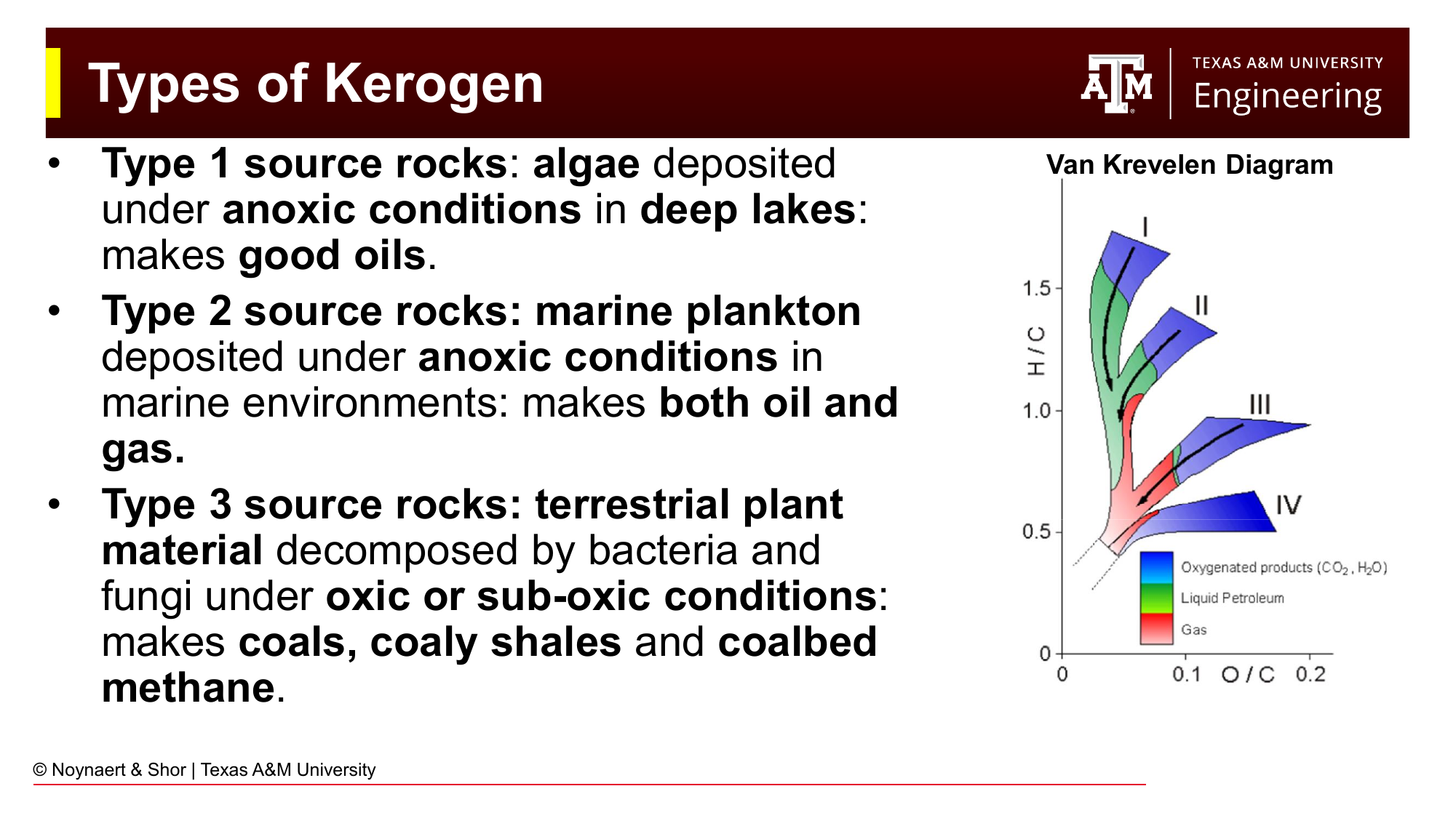
Fig. 2 Types of kerogen and the Van Krevelen diagram, which characterizes kerogen maturity by plotting the hydrogen-to-carbon (H/C) ratio against the oxygen-to-carbon (O/C) ratio. As kerogen matures with increasing burial temperature, it moves down and to the left on the diagram.#
Key Term: Kerogen
Kerogen is the solid, insoluble organic material found in sedimentary rocks. It is the precursor to oil and natural gas. When heated to sufficient temperatures during burial, kerogen undergoes thermal cracking to generate hydrocarbons.
1.3.3 The Oil and Gas Windows#
As burial depth increases, so does temperature. The conversion of kerogen to hydrocarbons is primarily a thermal process. Two temperature ranges are particularly important:
Oil window: approximately 60–160 °C (140–320 °F). Within this temperature range, kerogen thermally cracks into crude oil.
Gas window: approximately 150–200 °C (300–400 °F). At higher temperatures, remaining oil is cracked into lighter hydrocarbons, predominantly natural gas (methane).
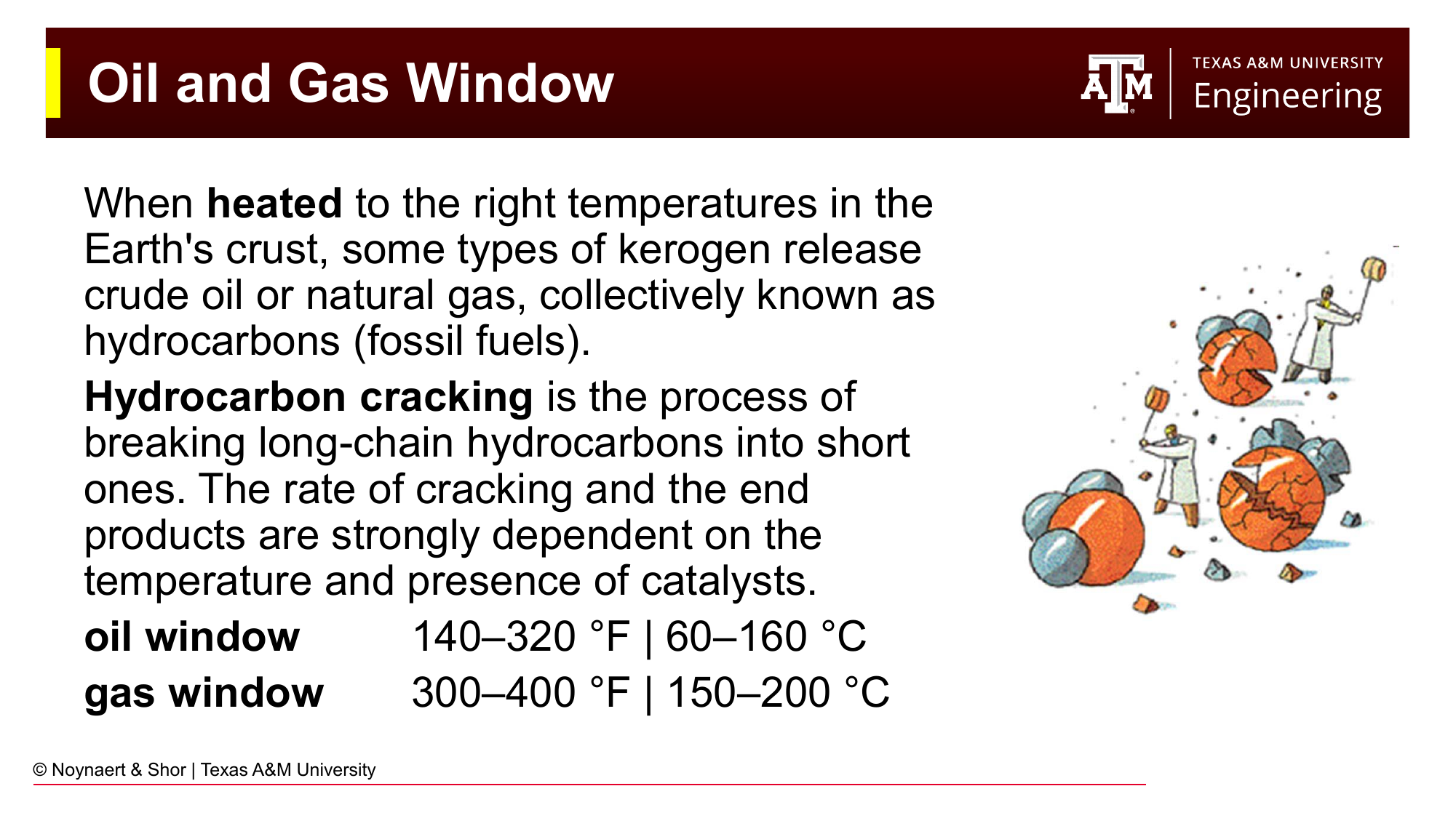
Fig. 3 The oil and gas windows. As burial depth and temperature increase, kerogen first enters the oil window and then the gas window, generating progressively lighter hydrocarbons. Source rocks buried below both windows contain only residual carbon (graphite).#
Rocks that are buried too shallow (too cool) may be immature — retaining their kerogen without generating significant hydrocarbons. Rocks buried too deep (too hot) will have cracked all hydrocarbons to dry gas or even graphite. The Van Krevelen diagram is a tool geochemists use to characterize kerogen type and maturity based on its hydrogen-to-carbon and oxygen-to-carbon ratios.
Key Term: Oil Window
The oil window refers to the range of subsurface temperatures (approximately 60–160 °C) at which buried kerogen thermally matures to generate crude oil. The analogous gas window (approximately 150–200 °C) describes conditions under which natural gas is generated.
1.3.4 Migration and Trapping#
Once generated, hydrocarbons migrate upward through permeable rock due to their lower density compared to the surrounding formation water. For an economically viable accumulation to exist, migrating hydrocarbons must encounter a trap — a combination of permeable reservoir rock and an overlying impermeable seal (cap rock) that prevents further upward migration and allows for accumulation of the hydrocarbon.
Structural traps are created by geological deformation. Faults are fractures in the Earth’s crust across which rocks have moved relative to one another, and can create barriers to fluid flow. Folds are bends in rock layers caused by compressional forces — anticlines (arch-shaped downfolds) are among the most common and productive structural traps in the world.
Stratigraphic traps are created not by deformation but by changes in the rock layers themselves: a permeable sandstone that becomes thinner (pinches out) laterally into impermeable shale, an ancient reef buried beneath sealing sediments, or an erosional surface (unconformity) that truncates a tilted reservoir layer. Stratigraphic traps are generally harder to find than structural traps because they may not produce an obvious geometric signature in seismic data.
Geologists organize these requirements into the concept of a petroleum system. A petroleum system consists of several components: a mature source rock, a migration pathway, a permeable reservoir rock, an impermeable seal, and a trap — all arranged in the correct sequence in both space and time. If any single element is missing, or if the trap formed after migration occurred, no accumulation exists. Exploration is fundamentally the search for locations where all elements of a petroleum system came together.
Key Term: Trap
A trap is a geological configuration in which permeable reservoir rock is overlain by an impermeable seal (cap rock), allowing hydrocarbons to accumulate rather than migrate to the surface. Common trap types include structural traps (anticlines, fault traps) and stratigraphic traps.
1.4 The Oil and Gas Value Chain#
The oil and gas industry is commonly divided into three broad segments based on the stage of the supply chain:
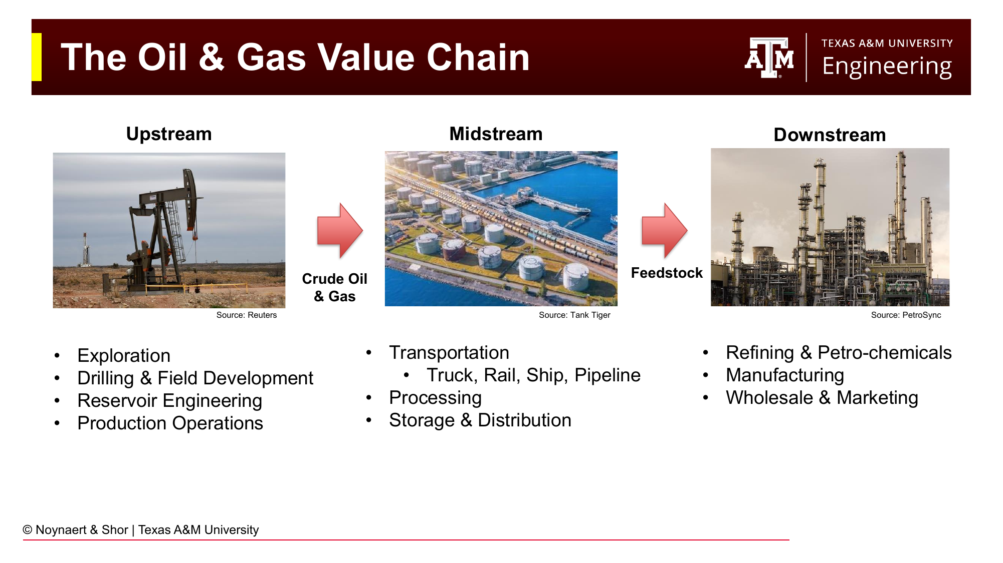
Fig. 4 The oil and gas value chain, divided into upstream (exploration and production), midstream (transportation and processing), and downstream (refining and marketing) segments.#
Upstream (Exploration and Production, E&P) — All activities related to finding, accessing, and producing crude oil and natural gas. This is the most capital-intensive, technically complex, and highest-risk segment. A common industry saying captures the scale: “Downstream’s budget is Upstream’s round-off error.”
Midstream — Transportation, processing, and storage of crude oil and natural gas. This includes pipelines, rail and tanker transport, compression and processing facilities, and storage terminals. Midstream companies generally operate on a fee-for-service basis with lower exposure to commodity price swings than upstream companies.
Downstream — Refining of crude oil into finished products (gasoline, diesel, jet fuel, plastics feedstocks, lubricants) and the marketing and distribution of those products to consumers.
Drilling engineering sits squarely within the upstream segment. Every barrel of oil or cubic foot of gas produced requires a wellbore drilled through rock to access the reservoir — making drilling a prerequisite for all other activity in the value chain.
1.5 The E&P Life Cycle#
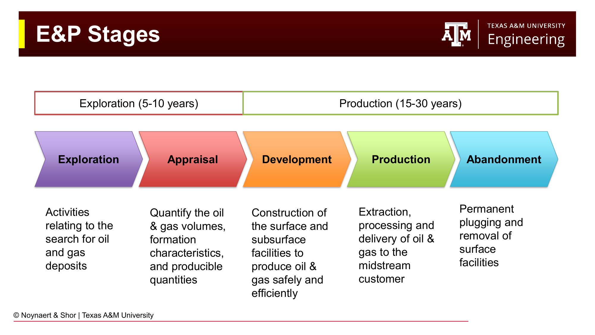
Fig. 5 The five stages of an E&P project lifecycle. The exploration and appraisal phases typically span 5–10 years; production typically lasts 15–30 years.#
An E&P project progresses through a series of well-defined stages, each with distinct activities, costs, and risk profiles. The full lifecycle from initial exploration to final abandonment can span 20–40+ years. There are plenty of examples of oil and gas fields across the world that have been producing oil and gas for 50+ years. The following sections discuss what typically occurs at each stage of the E&P Life Cycle, and how long that stage of the cycle typically lasts.
Exploration (5–10 years)#
Exploration activities focus on identifying where hydrocarbons may exist and evaluating whether the volumes and economics justify further investment. Key tools include:
Seismic surveys — sending sound waves into the Earth and recording reflections from subsurface rock boundaries to build a 3D image of the subsurface
Geological mapping — surface and subsurface mapping of rock types, structures, and stratigraphy
Exploration drilling — drilling one or more “wildcat” wells to physically sample the subsurface and test whether hydrocarbons are present
Exploration is inherently risky. Many exploration wells are dry holes that find no commercial hydrocarbons, and even large companies maintain drilling portfolios to spread this risk. Many governments support wild cat drilling through various financial schemes, ranging from insurance for dry holes to enabling of tax write-offs.
Appraisal#
If an exploration well encounters hydrocarbons, appraisal drilling follows to quantify the size of the accumulation, characterize the reservoir properties (porosity, permeability, fluid contacts), and determine whether production is economically viable.
Development#
Once a discovery is deemed commercially viable, the development phase begins. This is where the bulk of capital is deployed:
Target site selection — drilling locations are chosen based on geological and reservoir models
Site preparation — land is cleared and graded; for offshore, platforms or subsea infrastructure is installed
Drilling — a series of wells are drilled to access the reservoir from the chosen locations
Completion — each wellbore is completed to enable controlled production (casing, perforations, stimulation)
Production facilities — surface processing equipment is installed to handle produced fluids
Production (15–30 years)#
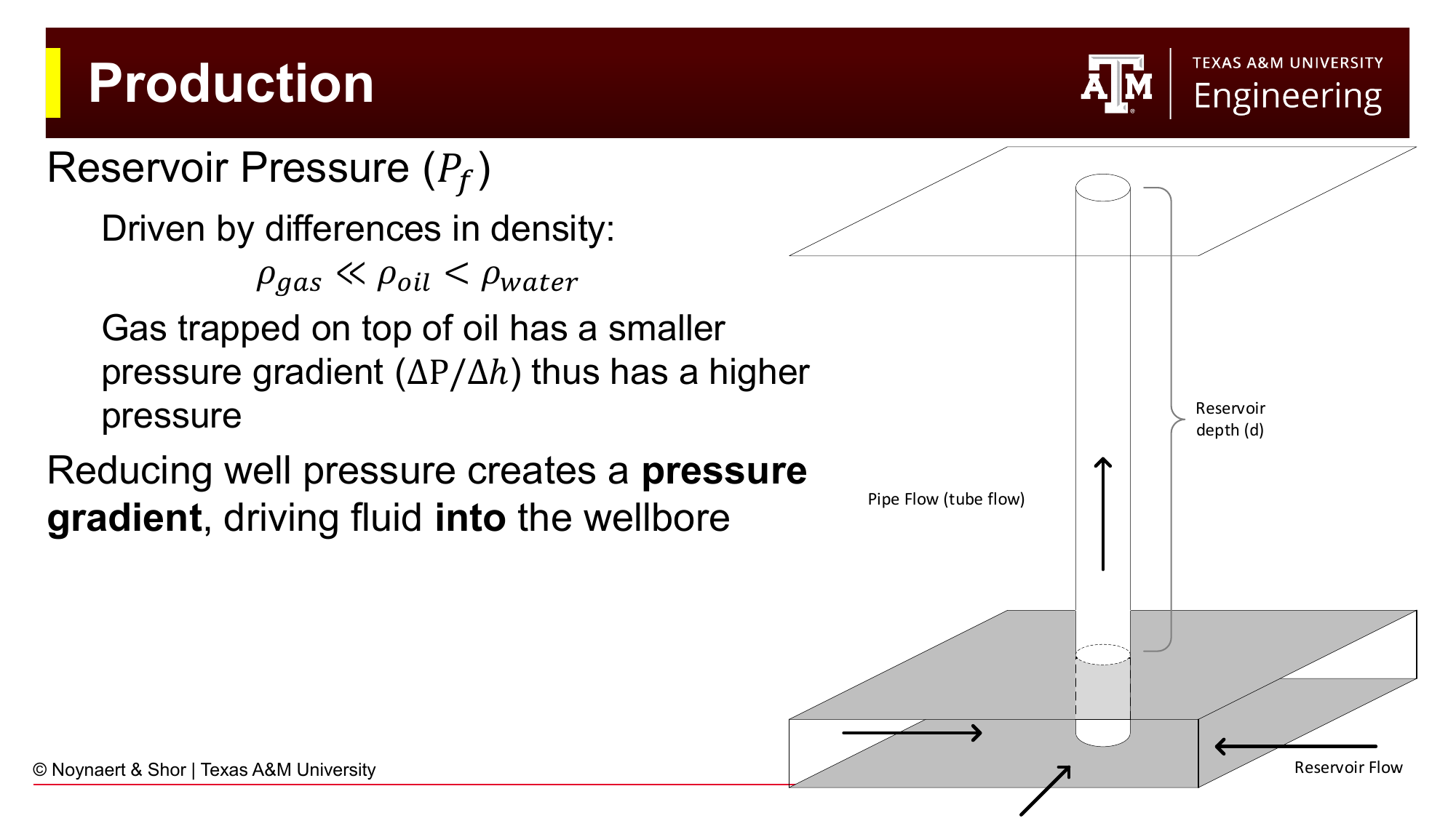
Fig. 6 Schematic of reservoir fluid production. Gas, having a lower density than oil or water, sits at the top of the reservoir at the highest pressure for a given depth. Reducing wellbore pressure below reservoir pressure drives fluid into the wellbore and up to surface.#
During the production phase, wells are brought online and hydrocarbons flow — initially driven by natural reservoir pressure, and later by artificial lift methods (pumps, gas lift) as reservoir pressure declines. Production engineers monitor well performance and optimize operations to maximize recovery over the field lifetime.
Abandonment#
At the end of field life, wells must be permanently plugged and surface facilities removed to restore the site. Regulations require that plugged wells are isolated so that no formation fluids can migrate to the surface or contaminate shallow aquifers. Well abandonment is a significant and growing cost center for the industry.
1.6 The Role of Drilling in E&P#
Drilling is the enabling technology of E&P. It is the only way to physically access subsurface formations — whether to sample rock and fluid, to prove the presence of hydrocarbons, or to produce them. The drilling process also creates the conduit (the wellbore) through which all subsequent operations — completions, production, injection — are conducted.
The drilling process involves far more than simply pushing a drill bit into the ground. A modern well is a precision-engineered structure designed to:
Maintain wellbore stability in a mechanically complex underground environment
Isolate multiple subsurface formations from one another (particularly protecting freshwater aquifers)
Control subsurface pressures to prevent blowouts
Steer the wellbore to reach a target that may be kilometers away horizontally from the surface location
This is achieved through a carefully designed casing and cementing program. The well is drilled progressively deeper, typically along a non-vertical wellpath, sections of steel pipe (casing) are installed and cemented in place to line the wellbore and provide zonal isolation. Directional drilling is discussed in Chapter 9, and casing and cementing design are developed in detail in Chapters 14–17.
Key Term: Wellbore
A wellbore is the hole drilled from the surface into the subsurface. It is typically lined with steel casing that is cemented in place, creating a conduit for production or injection fluids while isolating the different geological formations penetrated by the well.
1.6.1 A Typical Casing Program#
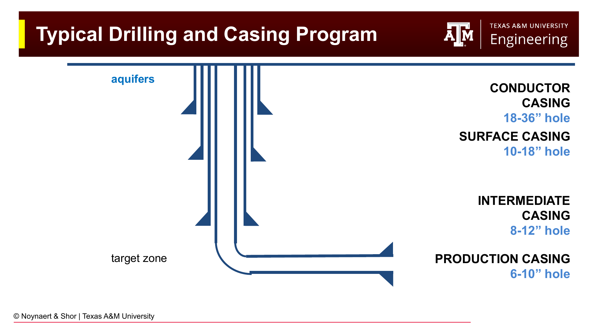
Fig. 7 A typical casing program for an onshore well. Each successive casing string is smaller in diameter and set deeper, isolating different geological zones including aquifers, unstable formations, and the target reservoir.#
A well is not drilled to the target depth in one pass. Instead, it is drilled in sections of increasing depth, with casing set and cemented at the end of each section. A typical program includes:
Conductor casing (18–36 inch diameter hole) — the first, shallowest casing string, installed to stabilize the near-surface soils and provide a foundation for the wellhead
Surface casing (10–18 inch hole) — set to isolate and protect shallow freshwater aquifers; the blowout preventer (BOP) stack is installed on this string
Intermediate casing (8–12 inch hole) — set to isolate troublesome formations (overpressured zones, unstable shales) encountered between surface and the target reservoir
Production casing or liner (6–10 inch hole) — run through the target reservoir zone and either cemented or left open to allow hydrocarbon production
Each casing string is smaller in diameter than the one above it, giving the well a characteristic tapered profile when viewed in cross-section.
1.6.2 Pressure Control#
One of the primary functions of the drilling fluid (also called “mud”) circulated during drilling is to provide hydrostatic pressure that balances the formation pore pressure. If the mud weight is too low, formation fluids may flow into the wellbore (a kick). If not controlled, a kick can escalate into a blowout — an uncontrolled release of formation fluids to surface. The 2010 Deepwater Horizon disaster, which killed 11 people and resulted in the largest marine oil spill in US history, was caused by a sequence of failures in well control. Pressure management is therefore a central theme throughout drilling engineering: well control fundamentals and kill procedures are covered in Chapters 7–9, and the Deepwater Horizon disaster and its consequences for the industry are examined in Chapter 21.
Key Term: Hydrostatic Pressure
Hydrostatic Pressure is the pressure exerted by the weight of the drilling fluid within the wellbore and is equal to the vertical depth, usually referred to as True Vertical Depth or TVD, multiplied by the density of the drilling fluid. The heavier the drilling fluid, the higher the hydrostatic pressure.
Key Term: Blowout
A blowout is an uncontrolled release of formation fluids (oil, gas, water) from a wellbore to the surface, occurring when pressure in the wellbore is lower than formation pressure. Blowout preventers (BOPs) are the primary mechanical safeguard against blowouts and are installed on the wellhead, typically once surface casing has been set and cemented.
1.7 Drilling Beyond Oil and Gas#
Although this course primarily addresses drilling in the context of the oil and gas industry, the underlying technology has broad applications wherever access to the subsurface is needed:
Geothermal energy — Hot water and steam found in permeable formations can be produced through wells and used to generate electricity or for direct heating. Geothermal wells are drilled using the same equipment and techniques as oil and gas wells, but may encounter higher bottomhole temperatures. A decade ago, drilling a geothermal well often took six to seven months; advances in drilling performance, many borrowed from oil and gas, have reduced this to as little as two to three weeks in some formations.
Water wells — Municipal and agricultural water supplies in many regions depend on wells drilled into aquifers. Water well drilling rigs are typically smaller and many are mounted on the back of trucks. Water wells are usually a few hundred to a thousand feet deep, and are usually drilled without the use of BOPs.
Mining — Directional drilling techniques are used to extract minerals from underground without large-scale excavation, or, in some cases boreholes are used to place explosives for surface or strip mining.
Critical minerals — There is growing interest in extracting lithium and other critical minerals from subsurface brines through drilled wells, supporting battery and clean energy supply chains.
CO₂ sequestration — Geologic carbon storage requires drilled injection wells to place captured CO₂, typically into deep saline formations.
The fundamental engineering challenges — pressure management, wellbore stability, fluid mechanics, drillstring mechanics — are common across all these applications. A drilling engineer trained on oil and gas wells has skills directly transferable to the growing geothermal and critical minerals sectors.
1.8 Overview of This Textbook#
This textbook serves both an introductory (sophomore-level) and an advanced (senior-level) drilling engineering course. After this foundational chapter, the book proceeds through six parts:
Part I — Foundations (Chapters 1–2) covers this introduction and the practice of drilling operations: rig systems, the five-step drilling process, and introduces the conept of the drilling window.
Part II — Drilling Fluids covers mud functions and classification, fluid property measurement and rheological models, and the calculations used to design and adjust mud systems.
Part III — Hydraulics and Well Control covers circulating system pressure losses and equivalent circulating density (ECD) and well control. Well control begins with kick detection, well shut-in, and well control procedures and techniques, and concludes with a quantitative kill calculation framework.
Part IV — Stresses and Wellbore Stability introduces directional drilling and survey calculations and covers geomechanics, wellbore stability, and the process of selecting casing setting depths
Part V — Tubulars covers stresses within tubulars, casing design, drillstring design, and the casing and cementing process.
Part VI — Professional Practice covers the Drill Well on Paper planning process and the industry’s social license to operate — the responsibilities that come with working in the subsurface.
Part VII — Advanced Topics covers drilling optimization through mechanical specific energy and the major drilling problems: lost circulation, stuck pipe, and fishing, geothermal drilling, and managed pressure drilling.
Throughout, the emphasis is on developing both conceptual understanding and practical calculation skills. Drilling engineers are expected to do accurate, well-documented calculations — mistakes in the field have serious consequences.
Worked Examples#
Example 1.1 — Hydrostatic Pressure Calculation#
Problem: A well is being drilled with a drilling fluid (mud) that has a density of 10.0 lb/gal (pounds per gallon). What is the hydrostatic pressure exerted by this mud column at a depth of 8,000 ft?
Solution:
Hydrostatic pressure in oilfield units is calculated as:
where:
\(P_h\) = hydrostatic pressure (psi)
\(\rho_{mud}\) = mud density (lb/gal or ppg)
\(TVD\) = true vertical depth (ft)
\(0.052\) = unit conversion factor (converts lb/gal and ft to psi)
Substituting values:
Interpretation: The mud column exerts 4,160 psi of pressure at 8,000 ft depth. This pressure must exceed the formation pore pressure at that depth to prevent formation fluids from entering the wellbore.
Example 1.2 — Oil and Gas Windows#
Problem: A geologist reports that a shale source rock has been buried to a depth where the temperature is approximately 180°C (356°F). What type of hydrocarbons would you expect this source rock to generate, and why?
Solution:
Recall the thermal windows:
Oil window: 60–160°C
Gas window: 150–200°C
At 180°C, the source rock is within the gas window. At these temperatures, the long-chain hydrocarbon molecules that form crude oil are thermally cracked into shorter-chain molecules, predominantly methane (natural gas). Any oil previously generated at shallower burial depths may also have been cracked to gas.
Conclusion: This source rock would be expected to generate primarily natural gas. An exploration program targeting this formation would focus on gas rather than oil.
Example 1.3 — Identifying E&P Phases#
Problem: A company has just drilled a well that encountered 50 feet of net oil pay in a sandstone reservoir at 9,000 ft depth. The well tested at 500 barrels of oil per day (BOPD). The company now wants to understand the size of the accumulation before committing to a full development. What phase of the E&P lifecycle is this, and what are the typical next steps?
Solution:
The initial discovery well has confirmed the presence of hydrocarbons and obtained a production test. The company does not yet know the areal extent of the reservoir or the total recoverable volume. This is the appraisal phase.
Typical next steps include:
Reprocessing and reinterpreting 3D seismic data around the discovery to map the reservoir geometry
Drilling one or more appraisal wells at offset locations to determine the reservoir boundaries and confirm that reservoir properties are consistent
Collecting additional core samples and running well logs to characterize porosity, permeability, and fluid saturations
Building a reservoir model to estimate recoverable reserves
Conducting an economic analysis to determine whether the discovery justifies full development investment
Practice Problems#
1.1 A drilling fluid has a density of 11.5 lb/gal. Calculate the hydrostatic pressure at depths of (a) 5,000 ft, (b) 10,000 ft, and (c) 15,000 ft. Express your answers in psi.
Solution
Use \(P_h = 0.052 \times \rho_{mud} \times TVD\):
(a) \(P_h = 0.052 \times 11.5 \times 5{,}000 = \mathbf{2{,}990 \text{ psi}}\)
(b) \(P_h = 0.052 \times 11.5 \times 10{,}000 = \mathbf{5{,}980 \text{ psi}}\)
(c) \(P_h = 0.052 \times 11.5 \times 15{,}000 = \mathbf{8{,}970 \text{ psi}}\)
1.2 A source rock sample is analyzed and found to have a Type II kerogen composition. The rock is currently at a burial depth where the temperature is 95°C. Answer the following:
(a) Is this rock within the oil window, gas window, or outside both?
(b) What type of hydrocarbon would you expect it to be generating?
(c) If tectonic activity caused additional burial increasing the temperature to 175°C, how would your answer change?
Solution
(a) At 95°C, the rock is within the oil window (60–160°C).
(b) Type II kerogen in the oil window generates crude oil (and associated gas). Type II generates both oil and gas across its maturity range, but oil dominates at lower temperatures within the window.
(c) At 175°C, the rock moves into the gas window (150–200°C). The kerogen would now predominantly generate natural gas. Any previously generated oil would have been thermally cracked to gas as well.
1.3 An oil company is drilling a vertical well that will require the following casing strings: 20-inch conductor (set at 200 ft), 13⅜-inch surface casing (set at 2,000 ft), 9⅝-inch intermediate casing (set at 9,000 ft), and 7-inch production casing (set at 12,500 ft, total depth).
(a) List the four hole sizes required, in order from largest to smallest.
(b) At what depth is the blowout preventer (BOP) typically installed, and on which casing string?
(c) What is the primary purpose of the surface casing string?
Solution
(a) The drilled hole must be larger than the casing to be run into it. Using typical relationships between casing and hole size:
Conductor section: ~26-inch hole
Surface casing section: ~17½-inch hole
Intermediate casing section: ~12¼-inch hole
Production casing section: ~8½-inch hole
(b) The BOP stack is installed on the surface casing string (the 13⅜-inch, set at 2,000 ft). This provides the mechanical foundation for well control equipment before drilling into the higher-pressure formations below.
(c) The primary purpose of surface casing is to isolate and protect shallow freshwater aquifers from contamination by deeper formation fluids or drilling fluids. It also provides structural support for the wellhead and BOP.
1.4 An energy company is evaluating two potential well targets in the same basin. Target A is a conventional sandstone reservoir at 8,000 ft depth with estimated reserves of 2 million barrels (MMbbl). Target B is a geothermal reservoir at 6,000 ft depth with a temperature of 175°C (347°F) and sufficient permeability to sustain a water flow rate of 50,000 barrels per day.
(a) For Target A, which phase of the E&P lifecycle would drilling the first well represent? What information would this well need to provide?
(b) For Target B, identify two ways in which geothermal well drilling differs from oil and gas drilling, and two ways in which it is similar.
Solution
(a) Drilling the first well into Target A would represent the exploration phase (a wildcat or exploration well). The well would need to:
Confirm the presence of hydrocarbons (oil shows, production test)
Measure reservoir pressure and temperature
Evaluate reservoir quality (porosity, permeability) via well logs and core samples
Establish the depth and thickness of the pay zone
Sample the fluids to characterize oil and gas composition
(b) Differences:
Geothermal wells typically have much larger diameters than onshore oil and gas wells due to higher productions rates, and must manage high-temperature steam and hot water
The target fluid (hot water/steam) has very low economic value per barrel compared to oil, so cost control is even more critical in geothermal
Similarities:
Both use rotary drilling equipment, drilling fluids, and the same basic drilling mechanics
Both require casing programs and cementing to isolate formations and protect aquifers
Both must manage wellbore pressure and stability
Both use similar drill bits, drill pipe, and surface equipment
1.5 The energy density of gasoline is approximately 34 MJ/l. A lithium-ion battery pack stores between 100 and 250 Wh/kg (watt-hours per kilogram). Given that 1 liter of gasoline weighs approximately 0.74 kg, calculate the mass of battery pack needed to store the same energy as 1 liter of gasoline. Comment on the significance of your result.
Solution
Energy in 1 liter of gasoline:
Convert to watt-hours: \(1 \text{ Wh} = 3{,}600 \text{ J}\)
Mass of battery needed at 250 Wh/kg:
Comparison: 1 liter of gasoline weighs 0.74 kg. Storing the equivalent energy in a lithium-ion battery requires approximately 37.8 kg — roughly 51 times heavier. This difference in energy density explains why liquid hydrocarbons remain dominant in transportation applications and highlights a key technological challenge for the electrification of vehicles, aviation, and shipping.
Summary#
This chapter has introduced the foundations of petroleum engineering and the E&P industry. The key points are:
Petroleum engineering addresses the full lifecycle of oil and gas development, from exploration through abandonment. Drilling engineering is the enabling technology that creates access to the subsurface.
Hydrocarbons originate from organic matter buried in sedimentary basins over geological time. Thermal maturation of kerogen, at temperatures corresponding to the oil window (60–160°C) or gas window (150–200°C), generates crude oil or natural gas.
For a commercial hydrocarbon accumulation to exist, a source rock, a reservoir rock, a seal (cap rock), and a trap must all be present simultaneously.
The oil and gas industry is divided into upstream (E&P), midstream (transport and processing), and downstream (refining and marketing) segments. Drilling is an upstream activity.
An E&P project progresses through exploration, appraisal, development, production, and abandonment phases, spanning 20–40 years in total.
A well is constructed through progressive drilling and casing, with each casing string isolating a section of the wellbore and providing pressure integrity.
Drilling technology applies beyond oil and gas to geothermal energy, water supply, critical minerals extraction, and CO₂ sequestration.
References#
Mitchell, R.F. and Miska, S.Z. (eds.), Fundamentals of Drilling Engineering, Society of Petroleum Engineers, 2011.
Al-Majed, A.A., Hossain, M.E., and Al-Majed, A., Fundamentals of Sustainable Drilling Engineering, John Wiley and Sons, 2015.