
Chapter 19 — Tubular Design: Casing#
Learning Objectives#
By the end of this chapter, students should be able to:
Identify the three primary failure modes for casing: burst, collapse, and tension.
Calculate the burst load on a casing string given the internal presure, pore pressure, and a design factor.
Calculate the collapse load on a casing string assuming the evacuated casing case.
Apply the buoyancy factor to determine the weight of a casing string in mud.
Calculate the tension load on a casing string and apply a design factor.
Select a casing grade and weight using API casing tables given calculated burst, collapse, and tension requirements.
Explain the von Mises (triaxial) combined loading criterion and identify when combined loading governs over uniaxial design.
19.1 Casing as a Pressure Vessel#
Once set and cemented, casing must withstand mechanical loads from multiple sources simultaneously. Unlike a beam or a column in structural engineering (which typically carries one dominant load), casing must simultaneously handle:
Internal pressure trying to burst it open from inside
External pressure trying to collapse it from outside
Axial tension from the weight of the string itself
Axial compression (in some scenarios) and bending in deviated wells
These loads are not independent: in reality, a highly tensioned casing string has lower collapse resistance than the same string under no axial load. The rigorous approach to accounting for combined loads is the triaxial (von Mises) design, developed in Section 19.9. For most routine casing design, we treat each load mode separately, a simplified approach called uniaxial design, and apply design factors to account for uncertainties.
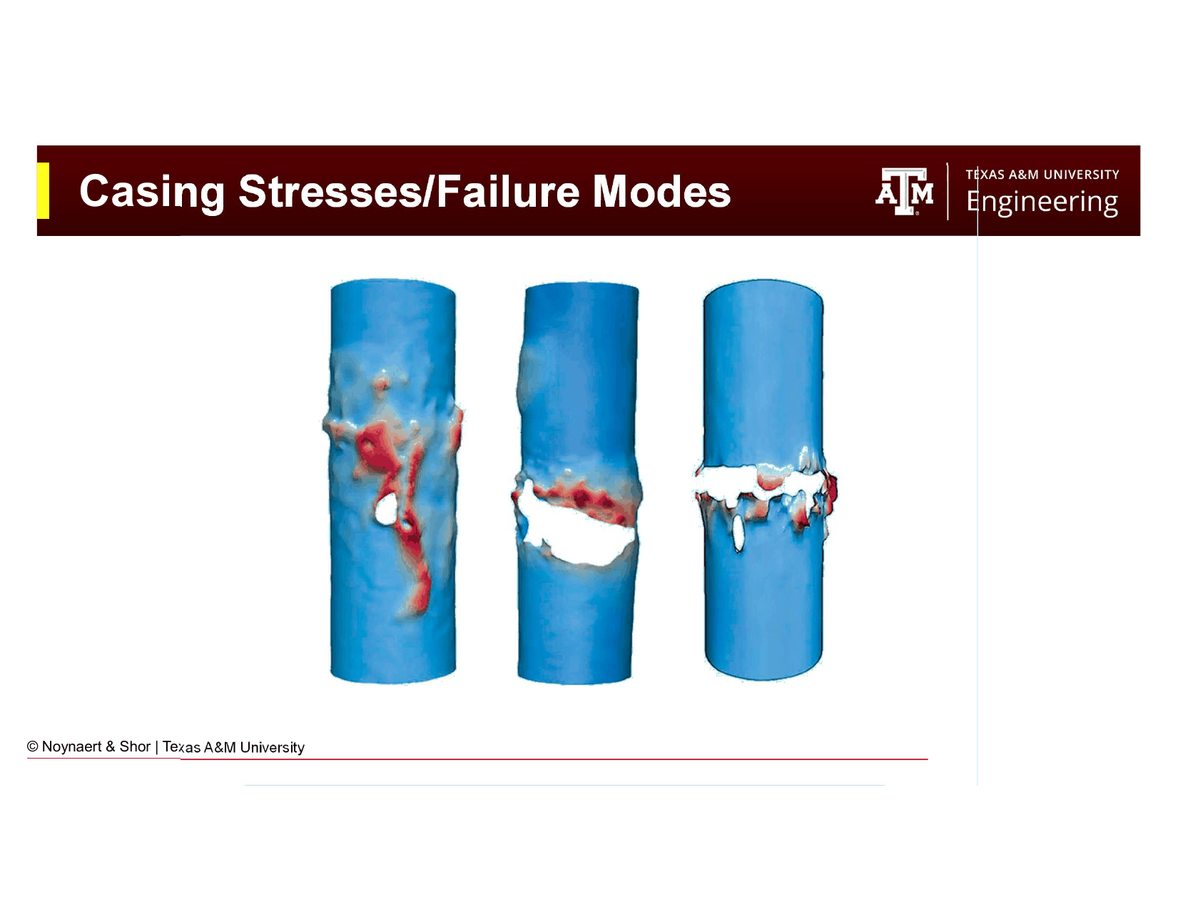
Fig. 229 The three primary casing stress modes: burst (internal pressure), collapse (external pressure), and tension (axial load).#
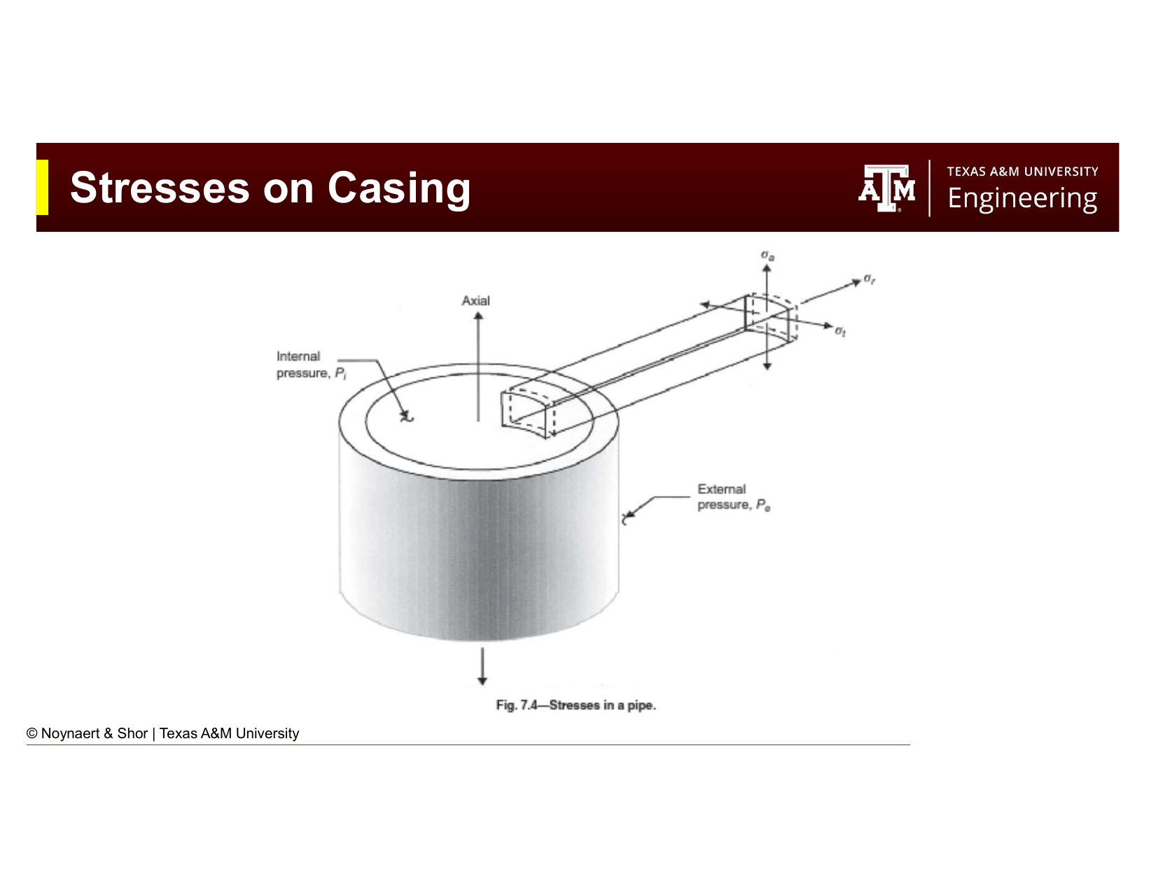
Fig. 230 Sources of loads and forces acting on casing throughout the life of the well.#
19.2 Failure Modes#
19.2.1 Burst#
Burst occurs when internal pressure exceeds the pipe’s capacity to contain it, causing the pipe to split or rupture. The driving force is pressure acting outward, from an influx while drilling, injection pressure, shut-in pressure while producing gas, or trapped annular pressure.
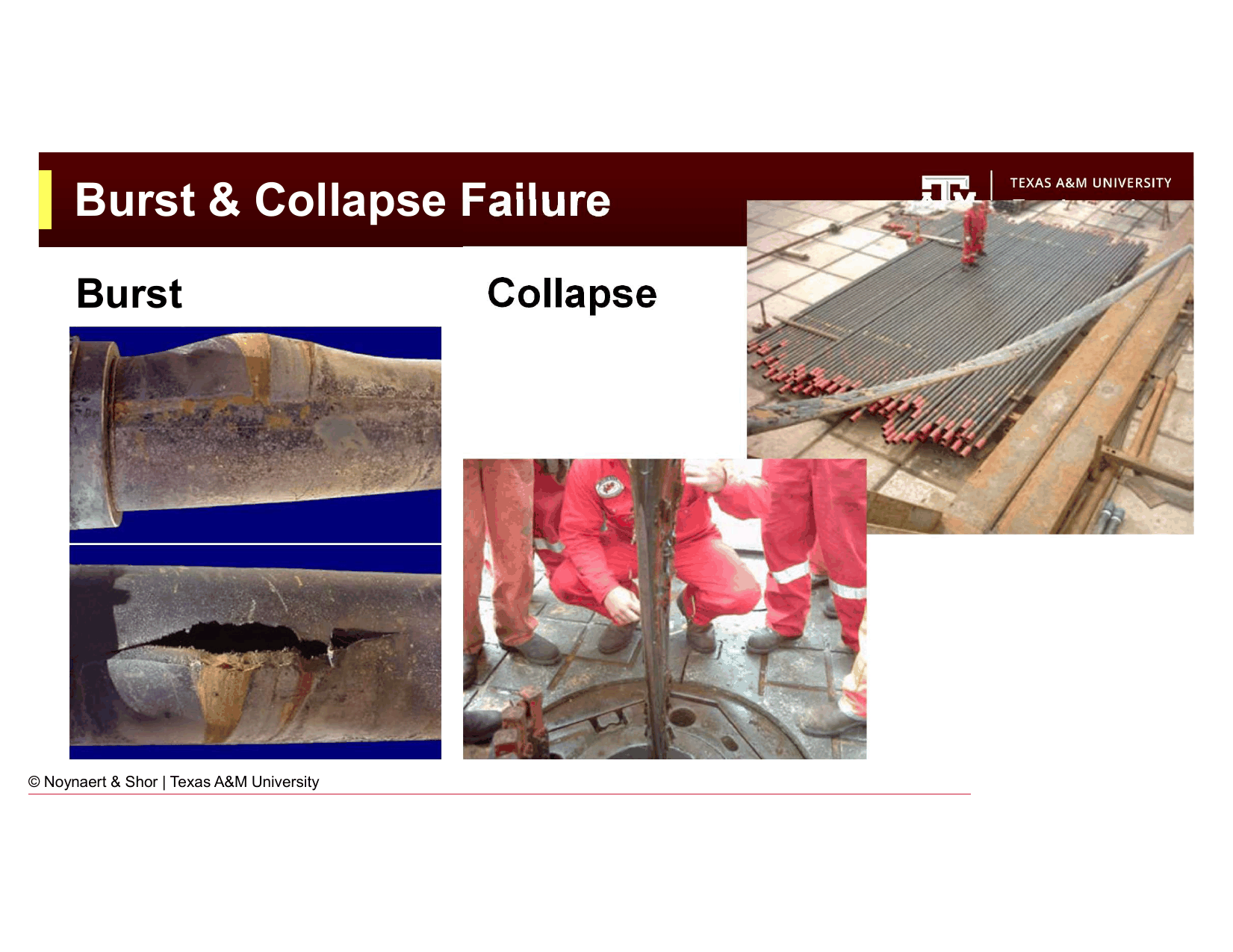
Fig. 231 Burst failure (left) results from internal pressure exceeding the pipe’s yield strength. Collapse failure (right) results from external pressure crushing the pipe wall inward.#
The burst load is greatest:
At shallow depths, where the formation pressure gradient may be high relative to the external pressure support from the mud column above
When the annulus is gas-cut or dry (reducing external pressure support)
During a well control event (kick) when formation pressure acts on the casing from inside
During stimulation (e.g., hydraulic fracturing) when treating pressures can be very high
During production when the casing is evacuted to gas and the well is shut in
The primary failure mode for burst is yield burst, the hoop stress in the pipe wall exceeds the yield strength of the steel and the pipe deforms plastically. For thin-walled pipe, this is approximated by the Barlow formula (also the basis for the API simplified burst equation):
where \(Y_p\) is the minimum yield strength (psi), \(t\) is the wall thickness (in), and OD is the outside diameter (in).
API casing tables report the internal yield pressure for each casing specification, which accounts for the wall thickness and grade.
19.2.2 Collapse#
Collapse occurs when external pressure exceeds the pipe’s resistance, causing inward deformation of the pipe wall. The driving force is external pressure acting inward, from the mud column, cement column, rock stresses and creeping formations, or formation pressure acting on the outside of the pipe.
Collapse load is greatest:
At deep depths, where the external hydrostatic pressure (from the mud column above) is highest
When the casing is empty (no internal fluid pressure to support the walls from inside)
In deviated sections where the pipe is not centralized and external pressure is concentrated
The collapse failure mode depends on the diameter-to-thickness ratio (D/t), also called the slenderness ratio:
Thick-walled pipe (low D/t): Fails by yield (Lame’s formula). The entire pipe wall yields before the geometry changes significantly.
Thin-walled pipe (moderate D/t): Fails by plastic collapse — partial yielding followed by geometric deformation.
Very thin-walled pipe (high D/t): Fails by elastic collapse (Euler-type buckling of the pipe cross-section).
API casing tables report the collapse pressure rating for each specification, accounting for the actual failure mode.
19.2.3 Tension#
Tension arises from the weight of the casing string below any point. The top joint of the string carries the full buoyant weight of all the pipe below it. As the string length and weight per foot increase, the tension at the top of the string increases.
Additional tension sources include:
Temperature differential (thermal contraction when cold fluid is circulated after cementing in a hot well)
Bending in deviated sections (the tension side of a bend is in tension; the compression side is in compression)
Shock load when the casing string is suddenly arrested (e.g., tags a ledge during running)
The failure mode for tension is pipe body yield or connection failure. API tables report pipe body yield strength (in lb) and joint strength for the connection (which is almost always the limiting element — connections are weaker than the pipe body in tension).
19.3 Design Factors#
Because real-world loads are uncertain (pore pressure estimates are imperfect, casing may be slightly undersized or have manufacturing defects, installation conditions are never ideal) and consequences of failure are severe, casing design uses design factors (also called safety factors) that require the rated capacity to exceed the calculated load by a margin.
Or equivalently, the design factor is the ratio of rated capacity to applied load, and it must exceed a minimum value:
Standard design factors for the uniaxial approach:
Load Mode |
Minimum Design Factor |
Typical Industry Practice |
|---|---|---|
Burst |
1.1 |
1.1–1.2 |
Collapse |
1.125 |
1.125–1.25 |
Tension |
1.3 |
1.3–1.8 |
Key Term
A design factor (safety factor) is the ratio of a casing string’s rated load capacity to the maximum anticipated applied load. Standard design factors are 1.1 for burst, 1.125 for collapse, and 1.3 for tension. A casing string is acceptable only if its rated capacity exceeds the design factor times the calculated load for all three modes simultaneously.
These values are minimum industry standards. Regulatory requirements, company policies, and specific risk assessments may mandate higher design factors in critical or high-consequence wells.
19.4 Burst Load Calculation#
For the simplified uniaxial burst design, the burst pressure acting on the casing is the net internal pressure: the internal pressure from formation fluids minus any external pressure support from fluid in the annulus.
For the worst-case burst assumption, we assume:
The casing is full of gas from the formation (gas kicks represent the highest pressure influx because gas is compressible and its gradient is much lower than mud)
The annulus provides some external pressure support equal to the mud hydrostatic at that depth
In practice, for a simplified calculation:
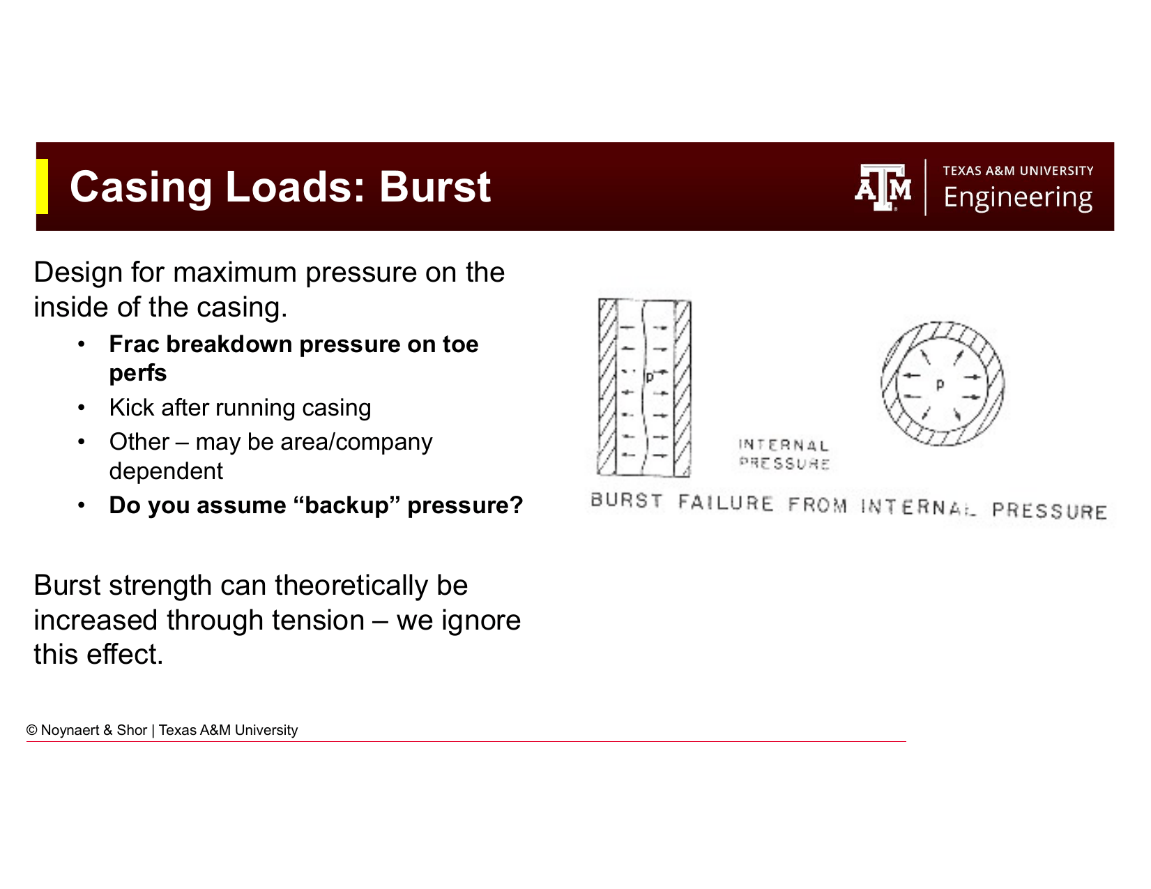
Fig. 232 Burst load calculation: the net internal pressure is the formation pressure minus external annular pressure support.#
where:
\(\text{PP}_\text{ppg}\) = pore pressure equivalent mud weight at the depth of interest (ppg)
\(\text{TVD}\) = true vertical depth (ft)
\(0.052\) = conversion factor (psi per foot per ppg)
\(DF_\text{burst}\) = burst design factor (minimum 1.1)
This gives the minimum internal yield pressure the casing must provide. The selected casing must have:
Note
The simplified burst formula above represents a conservative worst-case: it assumes the full formation pressure acts on the inside of the casing with no external support. More rigorous analysis applies net burst pressure: external pressure from the mud or cement column is subtracted, and the casing is analyzed at both the surface and the shoe to find the critical location.
19.5 Collapse Load Calculation#
For the simplified uniaxial collapse design, we use the evacuated casing assumption: the casing is assumed to be completely empty inside (no internal fluid pressure). This is a conservative worst case: it can occur when a producing well is shut in and the casing is vented, or during cementing operations if the casing fails to fill with fluid.
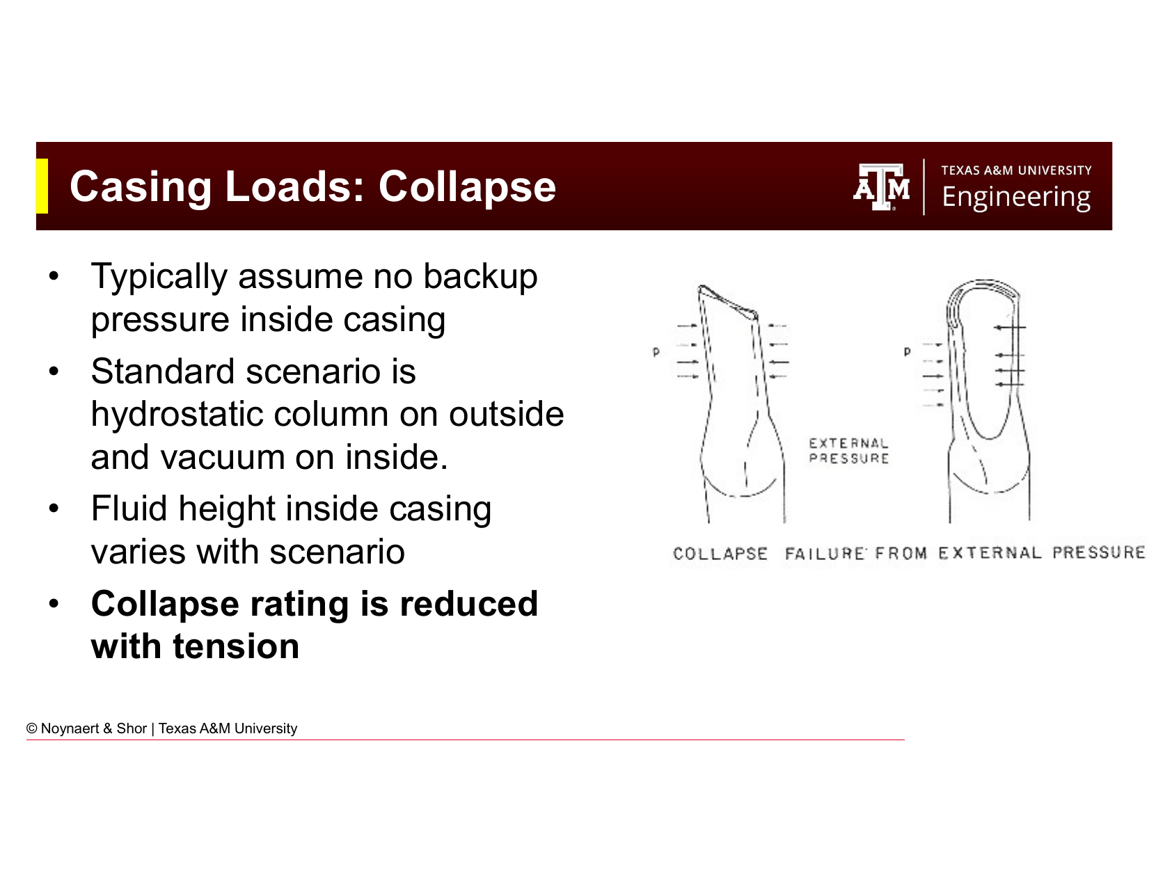
Fig. 233 Collapse load: the external pressure at depth is the hydrostatic pressure of the mud column, assumed to act on an empty casing.#
where:
\(\text{MW}_\text{ppg}\) = mud weight (ppg) — the fluid in the annulus providing external pressure
\(\text{TVD}\) = true vertical depth of the depth of interest (ft)
\(DF_\text{collapse}\) = collapse design factor (minimum 1.125)
The selected casing must have:
19.6 Tension Load Calculation#
The axial tension load at any point in the casing string equals the weight of all the pipe below that point. At the top of the string, the tension is greatest:
where:
\(w_\text{nom}\) = nominal weight per foot of the casing (lb/ft)
\(L_\text{total}\) = total length of the string (ft)
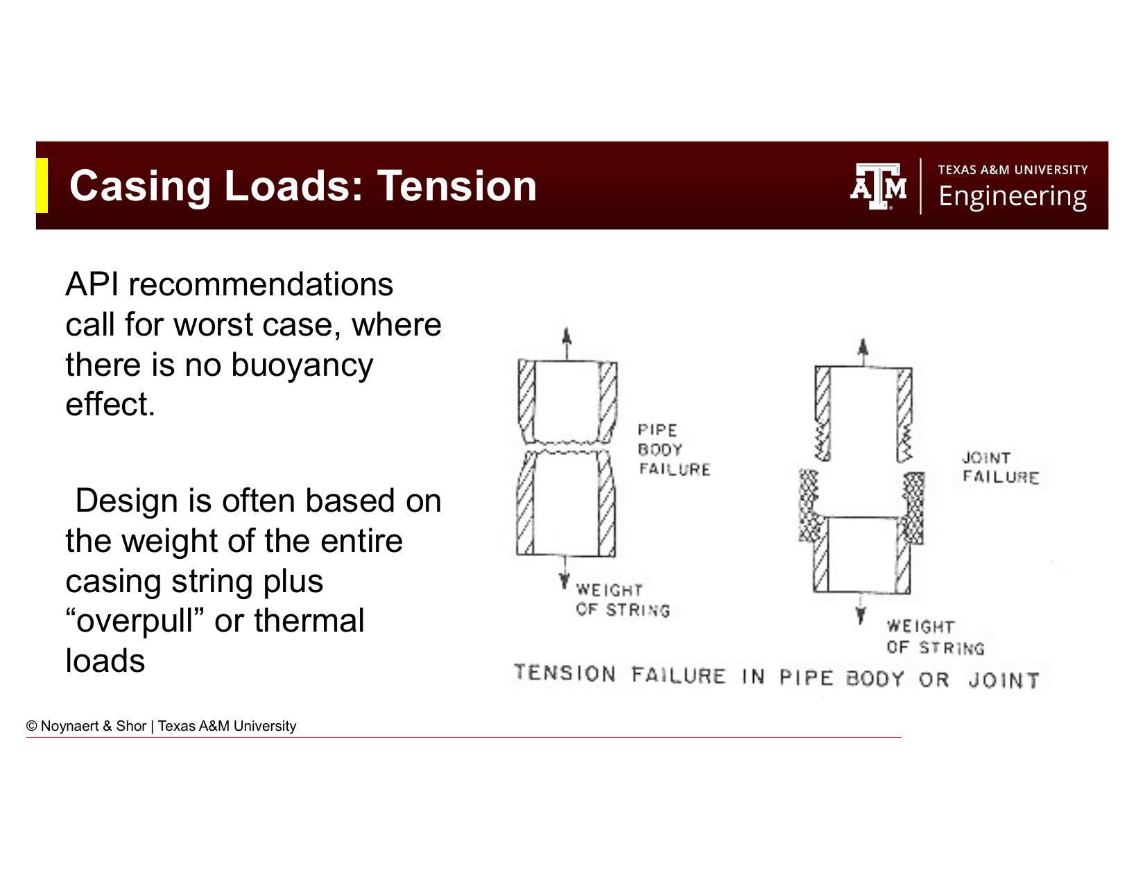
Fig. 234 Tension load in casing: the top of the string carries the full weight of all pipe below.#
The selected casing joint (connection) must have:
19.6.1 Buoyancy Factor#
When casing is submerged in a fluid, in our case, drilling mud, the mud exerts a buoyant upward force that partially offsets the pipe weight. The buoyancy factor is:
The buoyancy factor is usually between 0.7 and 0.95, depending on the density of the fluid.
Key Term
The buoyancy factor \(k_B\) accounts for the upward buoyant force exerted by the mud on the casing string. The buoyed weight of the casing (the tension the hook must support while running) equals the air weight times the buoyancy factor: \(F_\text{buoyed} = k_B \times F_\text{air}\).
The buoyed weight is what the rig’s hookload actually is:
For tension design, the question is: is the top joint of casing strong enough to support the full buoyed weight plus any overpull that may be needed to free the string if it becomes stuck during running.
For collapse design, buoyancy reduces the effective external pressure, but the conservative evacuated-casing assumption already ignores any internal pressure, so the simplified approach does not require buoyancy correction for collapse.
For tension design factor application:
The design factor of 1.3 is typically applied to the air weight (not buoyed weight) in some company standards, to be conservative. Others apply it to the maximum hookload anticipated (air weight plus overpull allowance). Always confirm which convention applies.
19.7 Casing Tables and Selecting a Casing String#
API casing tables list, for each combination of OD, nominal weight, and grade, the following mechanical properties:
Internal yield pressure (burst rating), psi
Collapse pressure rating, psi
Pipe body yield strength (tension), lb
Joint strength (connection-dependent), lb
Nominal ID (in)
Drift diameter (in)
Wall thickness (in)
The design procedure is to calculate the minimum required burst, collapse, and tension capacities (including design factors), then search the table for a casing specification that satisfies all three simultaneously with the same or higher rated capacity.
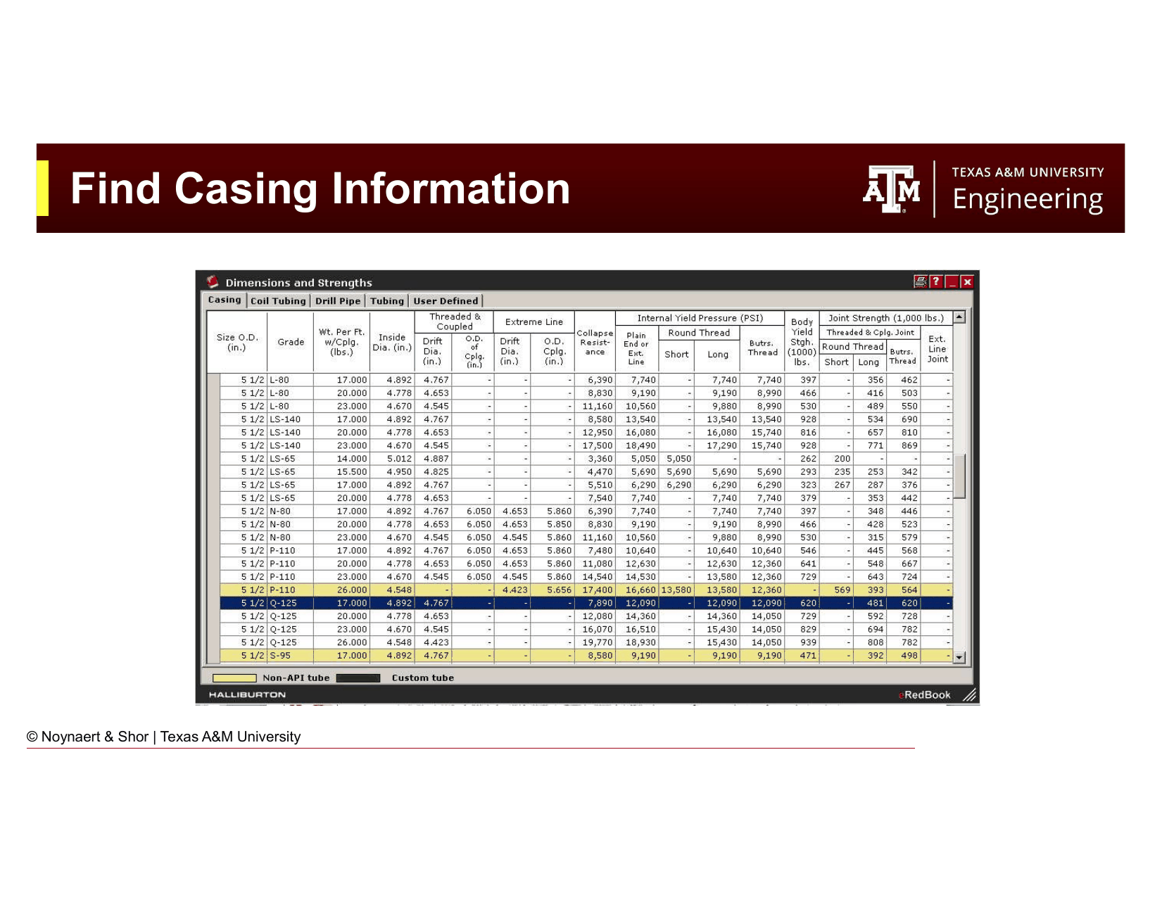
Fig. 235 API casing tables provide rated capacities for each combination of OD, weight, and grade. The engineer selects the lightest (cheapest) string that satisfies all three load requirements.#
19.8 Worked Example: 5½ in Production Casing, 15,000 ft#
This example follows directly from the lecture slides.
Given:
Well depth: 15,000 ft TVD (vertical well)
Pore pressure: 17.2 ppg EMW
Mud weight: 18.0 ppg
Production string: 5½ in OD
Step 1: Calculate the burst load requirement
The casing must have an internal yield pressure ≥ 14,758 psi.
Step 2: Calculate the collapse load requirement
The casing must have a collapse pressure rating ≥ 15,795 psi.
Step 3: Calculate the tension load requirement
The casing connection must have a joint strength ≥ 448,500 lb.
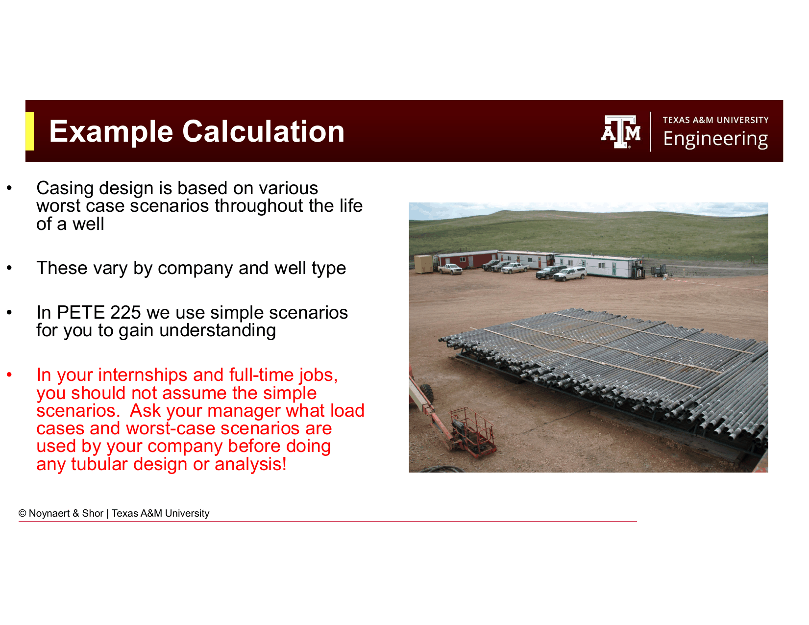
Fig. 236 The example calculation shows each design requirement for the 5½ in production string.#
Step 4: Find a satisfying casing specification
From API tables for 5½ in casing:
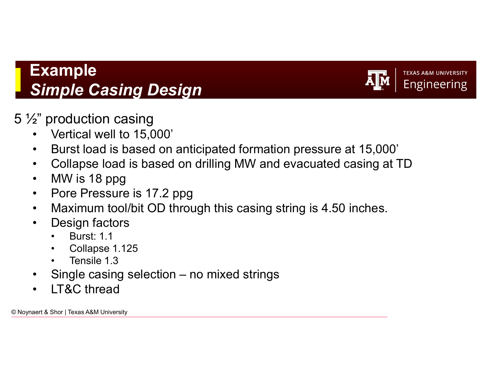
Fig. 237 Excerpt from API tables for 5½ in casing. For each weight and grade, the burst, collapse, and tension ratings are listed.#
After reviewing the table:
5½ in × 23 lb/ft × Q125 × Buttress:
Internal yield pressure: check table
Collapse resistance: check table
Joint strength: check table
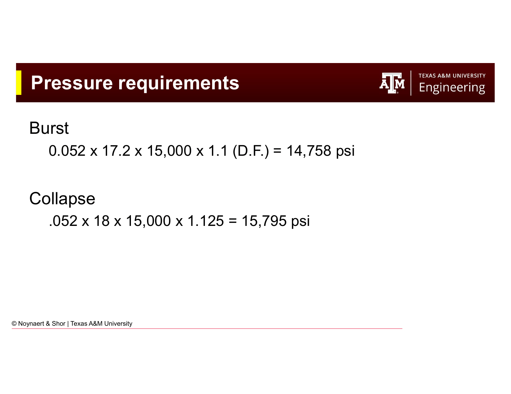
Fig. 238 Checking the pressure requirements against API table values for the selected casing.#
For this example from the slides:
Burst requirement: 14,758 psi
Collapse requirement: 15,795 psi
Tension requirement: 448,500 lb
The 5½ in × 23 lb/ft × Q125 with buttress connection satisfies all three requirements:
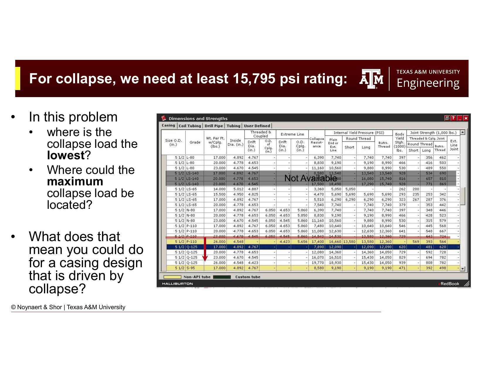
Fig. 239 Verifying the selected casing meets collapse requirements.#
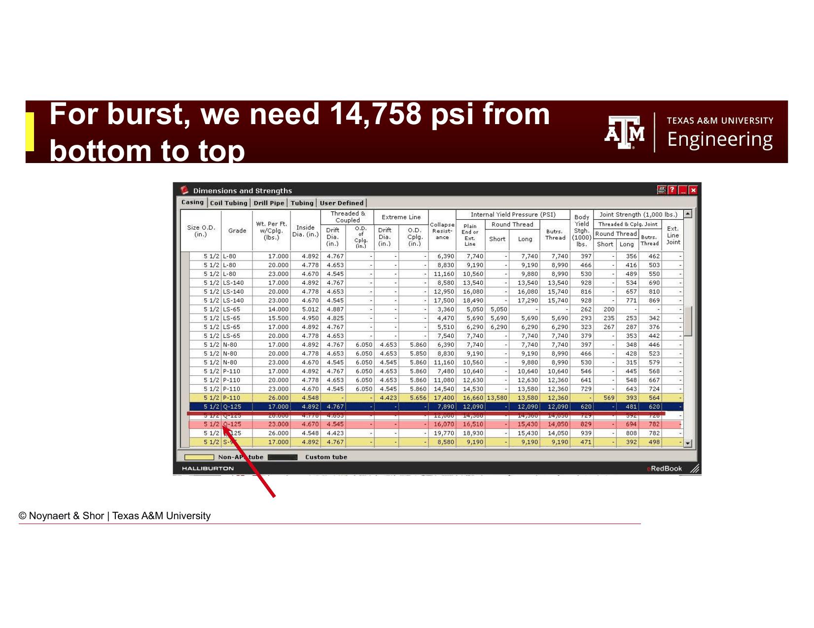
Fig. 240 Verifying the selected casing meets burst requirements.#
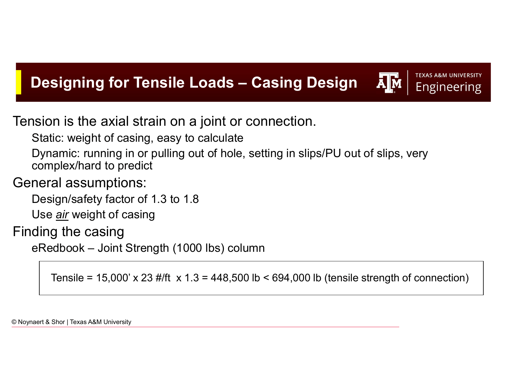
Fig. 241 Verifying the selected casing meets tension requirements. The joint strength of 694,000 lb exceeds the design requirement of 448,500 lb. ✓#
Result: 5½ in × 23 lb/ft × Q125 × Buttress casing is acceptable for this design.
Key Point
Note that collapse governs this design (15,795 psi required, which is the tightest constraint). This is typical of deep, high-mud-weight wells with production strings where the collapse load from the heavy mud column dominates. On shallower wells, burst often governs.
19.9 Triaxial Design and Combined Loads#
The uniaxial approach — treating burst, collapse, and tension as independent — is a simplification. In reality, loads interact: a pipe under high axial tension has a reduced collapse resistance, and bending in a deviated well adds stress that the uniaxial approach ignores entirely. When these combinations matter, the engineer must use a combined loading criterion. The von Mises criterion (also called the triaxial or VME criterion) is the industry standard for rigorous tubular design.
A complete analysis of the loads on a tubular in a deviated well requires considering four components acting simultaneously:
Axial load: The net weight of all tubular below a given cross-section, modified by buoyancy. At any point in the string, the axial stress is the net force divided by the pipe cross-sectional area.
Bending stress: A deviated wellbore bends the pipe. The outer wall of the bend sees additional tension; the inner wall sees compression. For a dogleg severity (DLS) in degrees per 100 ft and pipe OD in inches:
This is additive to axial tension on the outer wall, the critical location. The highest combined load in a build-and-hold well occurs at the top of the build section, where axial load is greatest (the full string hangs below) and bending begins.
Torsional load: Rotating the string against friction and bit reactive torque applies a shear stress to the pipe wall. Torsion is a secondary effect for casing design but important for drill pipe in deviated wells. In the design process, either the maximum expected torque is calculated, or the torque limit or make-up torque of the casing is used.
Pressure loads: Net internal pressure (burst) and net external pressure (collapse) as analyzed in the uniaxial approach.
19.9.1 The Von Mises (Triaxial) Criterion#
The von Mises criterion (also the triaxial criterion) provides the most rigorous way to check whether a casing string will yield under combined loads. It uses the three principal stresses at any point in the pipe wall to compute a single equivalent stress that can be compared to the yield strength:
where \(\sigma_1\), \(\sigma_2\), \(\sigma_3\) are the principal stresses (hoop, axial, and radial).
Failure occurs when \(\sigma_e \geq Y_p\) (minimum yield strength).
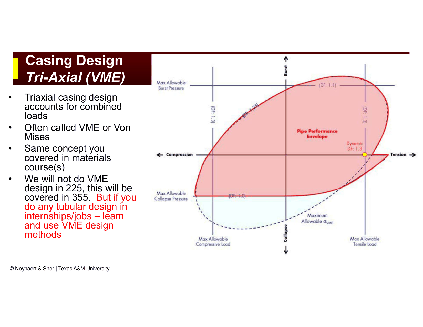
Fig. 242 The von Mises equivalent stress criterion for combined loading. The uniaxial design approach is conservative compared to the ellipse shown here, but not always on the safe side for all combined load cases.#
19.9.2 When Triaxial Design is Required#
The uniaxial design approach is non-conservative in several important scenarios:
HP/HT wells: Temperatures above ~300°F reduce steel yield strength, and thermal expansion of trapped fluids generates annular pressure loads that the uniaxial burst and collapse calculations do not capture.
Simultaneous burst and tension: On deep gas wells under high pore pressure with very long strings, burst and tension interact. The API collapse rating already implicitly accounts for the biaxial tension-collapse interaction (via the API collapse envelope), but the engineer must check both the uniaxial ratings and the biaxial interaction explicitly in these cases.
Significant bending: Horizontal or S-profile wells impose bending stress on the pipe wall. The bending stress \(\sigma_b \approx 218 \times \text{DLS} \times \text{OD}\) adds to or subtracts from the axial stress depending on which wall is being considered, and the combined state must be checked with the von Mises criterion.
Production strings in HP/HT reservoirs: Annular pressure buildup (APB) in a sealed annulus can become the governing collapse load case.
In each of these situations, compute the equivalent stress \(\sigma_e = \sqrt{(\sigma_A + \sigma_b)^2 + 3\tau^2}\) at the critical cross-section and verify that \(\sigma_e \times \text{DF} \leq Y_p\).
19.9.3 Annular Pressure Buildup (APB)#
When cement is placed in the annulus between two casing strings, a sealed annulus is created. If the well heats up during production, the trapped fluid expands and pressure builds in the annulus. This annular pressure buildup (APB) can add significant external collapse loading to the inner string — in deepwater HP/HT wells, it is often the controlling collapse load case.
Mitigations include: selecting casing strings with higher collapse ratings than the uniaxial case requires, installing burst discs or subsea pressure relief valves in the annulus to limit maximum APB, or using foam cement with compressibility to absorb expansion. For routine well designs, the uniaxial approach is a good starting point; the engineer escalates to a full triaxial analysis with APB when well conditions warrant.
19.10 Special Design Considerations#
19.10.1 H₂S and Sour Service#
As introduced in Chapter 17, H₂S requires special grade selection. In addition, sour service affects the design factor:
Standard collapse and burst calculations apply, but only sour-service grades (L80, C90, T95) may be used
Some company standards require a higher design factor for sour service (e.g., 1.2 for burst instead of 1.1)
The concentration threshold for H₂S service is defined by NACE MR0175/ISO 15156
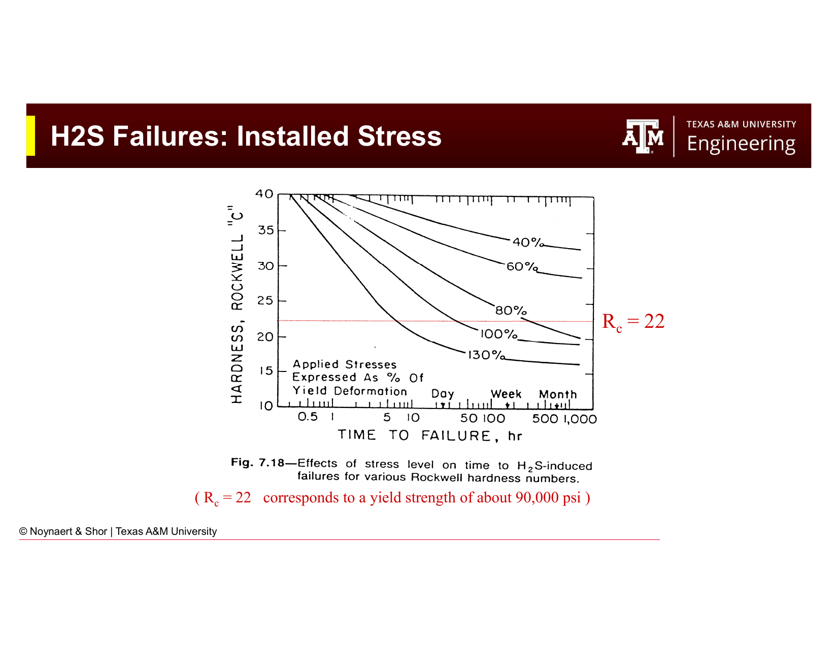
Fig. 243 Sulfide stress cracking (SSC) failure mode. High-strength grades (P110, Q125) are susceptible to sudden failure at stresses well below yield in H₂S environments.#
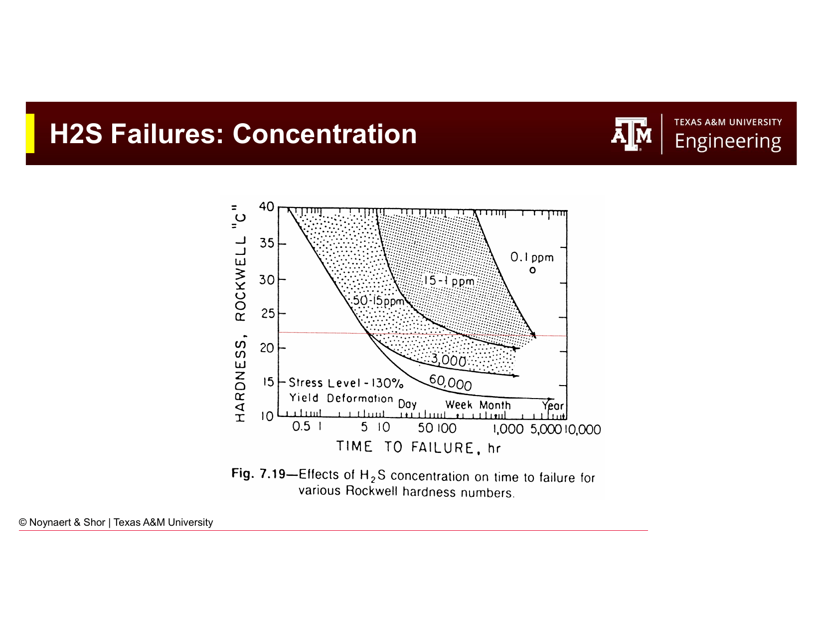
Fig. 244 H₂S concentration thresholds for sour service classification per NACE MR0175.#
19.10.2 High-Pressure / High-Temperature (HP/HT) Wells#
Wells with bottomhole temperatures exceeding ~300°F (150°C) or bottomhole pressures exceeding ~10,000 psi SITP require additional consideration of:
Temperature-dependent yield strength reduction (steel is weaker at elevated temperature)
Thermal expansion loads from temperature cycling between drilling and production
APB in sealed annuli
High-strength grades (P110, Q125) subject to brittleness limitations at extreme conditions
19.10.3 Slim-Hole Wells#
In slim-hole designs with very tight casing-to-casing clearances, the coupling OD of the running string may approach the drift ID of the outer string. In these cases, flush-joint or integral-joint connections eliminate the coupling OD and are required to maintain clearance.
Chapter Summary#
Casing design requires that every string satisfy three independent load requirements, burst, collapse, and tension, each multiplied by its corresponding design factor:
The buoyancy factor \(k_B = 1 - \text{MW}_\text{ppg}/65.5\) reduces the effective hookload during running but does not change the design calculation for burst and collapse. API casing tables provide rated capacities for each combination of OD, weight, and grade; the engineer selects the lightest string that simultaneously satisfies all three requirements.
Uniaxial design is adequate for most wells. For HP/HT wells, wells with significant bending, or cases where APB governs, the von Mises triaxial criterion \(\sigma_e = \sqrt{(\sigma_A + \sigma_b)^2 + 3\tau^2}\) provides a rigorous check that accounts for combined loading.
Chapter 20 covers drillstring design: the complementary problem of designing the drill pipe and drill collar assembly that connects the bit to the rig. Many of the same tools (buoyancy factor, tensile load calculation, safety factor) carry over, but the design goals differ: instead of containing wellbore pressure, the drillstring must deliver weight on bit without buckling while surviving the bending and torsion of a deviated well.
Key Equations Summary#
Load Mode |
Design Load |
Required Capacity |
Design Factor |
|---|---|---|---|
Burst |
\(P_b = 0.052 \times \text{PP} \times \text{TVD}\) |
\(\geq P_b \times 1.1\) |
1.1 |
Collapse |
\(P_c = 0.052 \times \text{MW} \times \text{TVD}\) |
\(\geq P_c \times 1.125\) |
1.125 |
Tension |
\(F_t = w \times L\) |
\(\geq F_t \times 1.3\) |
1.3 |
Buoyancy factor |
\(k_B = 1 - \text{MW}/65.5\) |
— |
— |
Buoyed weight |
\(F_\text{buoyed} = k_B \times F_\text{air}\) |
— |
— |
Practice Problems#
19.1. A 9⅝ in intermediate casing string is to be set at 8,500 ft TVD in a vertical well. The mud weight is 11.5 ppg and the pore pressure at the casing shoe is 10.2 ppg EMW. The nominal weight of the casing is 40 lb/ft.
(a) Calculate the minimum burst pressure rating required (DF = 1.1).
(b) Calculate the minimum collapse pressure rating required (DF = 1.125, assume evacuated casing).
(c) Calculate the minimum joint strength required (DF = 1.3, use air weight).
(d) Calculate the buoyancy factor and the buoyed weight of the string.
19.2. A casing design problem requires burst ≥ 9,800 psi, collapse ≥ 8,400 psi, and tension ≥ 280,000 lb. Using the simplified API table below, select the lightest casing string that meets all three requirements.
OD (in) |
Weight (lb/ft) |
Grade |
Burst (psi) |
Collapse (psi) |
Joint Strength (lb) |
|---|---|---|---|---|---|
7 |
17 |
J55 |
4,980 |
2,650 |
280,000 |
7 |
23 |
N80 |
8,600 |
7,020 |
436,000 |
7 |
26 |
N80 |
9,890 |
9,010 |
487,000 |
7 |
29 |
P110 |
13,610 |
10,780 |
598,000 |
7 |
32 |
P110 |
15,230 |
13,830 |
661,000 |
7 |
26 |
L80 |
9,890 |
9,010 |
487,000 |
7 |
29 |
L80 |
11,090 |
10,780 |
544,000 |
(a) Which strings satisfy burst?
(b) Of those, which also satisfy collapse?
(c) Of those, which also satisfy tension?
(d) What is the lightest string that satisfies all three constraints?
(e) The well has 20 ppm H₂S in produced gas. Does your selection change? Why or why not?
19.3. A 5½ in production casing string is to be set at 10,000 ft TVD in a vertical well with a pore pressure of 13.5 ppg EMW and a mud weight of 14.0 ppg. The nominal weight is 17 lb/ft.
(a) Calculate burst, collapse, and tension design loads including design factors.
(b) Calculate the buoyancy factor for 14.0 ppg mud.
(c) What is the hookload when the string is fully submerged in mud (air weight × buoyancy factor)?
(d) Which design load is highest relative to typical casing ratings? (Hint: compare to typical rated values for this size.)
19.4. A drilling engineer is designing production casing for a high-pressure well with pore pressure 16.8 ppg at 18,000 ft TVD. The mud weight is 17.5 ppg, and the nominal weight of the 5½ in casing is 23 lb/ft.
(a) Calculate the burst requirement.
(b) Calculate the collapse requirement.
(c) Calculate the tension requirement.
(d) The engineer selects 5½ in × 23 lb/ft × Q125. Is Q125 an API-standard grade? What is its minimum yield strength?
(e) The formation contains 80 ppm H₂S. Can Q125 be used? What grades are available options for sour service at similar yield strengths?
19.5.
(a) Explain why a casing string under high axial tension has lower effective collapse resistance than the same string under zero axial load.
(b) Describe a specific well scenario where ignoring this interaction (using the uniaxial approach) could lead to an unsafe design.
(c) What design criterion is used to properly account for combined burst/collapse/tension loading?