
Chapter 21 — Cementing#
Learning Objectives#
By the end of this chapter, students should be able to:
Explain the primary objective of primary cementing.
Describe the chemical composition of Portland cement and explain how hydration transitions it from a slurry to a solid.
Identify the API cement classes and explain why Class G and Class H are the industry workhorses.
Describe the effect of downhole temperature and pressure on cement setting behavior.
Identify and describe the function of each piece of cementing equipment: float shoe, float collar, bottom plug, top plug, stage collar, and centralizer.
Describe the step-by-step procedure for a primary cement job.
Perform basic cementing calculations: volume of cement, mixing water requirement, displacement volume.
Interpret cement evaluation methods: lift pressure, temperature log, and cement bond log (CBL).
21.1 Why Cementing Matters#
Among all the materials and operations in well construction, cement represents a tiny fraction of the total cost, typically 2–5% of the well budget. Yet poorly cemented wells are responsible for a disproportionate share of well integrity failures, environmental incidents, and production problems. Zonal isolation failures are the leading cause of sustained casing pressure (gas migrating between zones through the annulus) and surface casing vent flows (gas or water flowing outside the production casing to the surface).
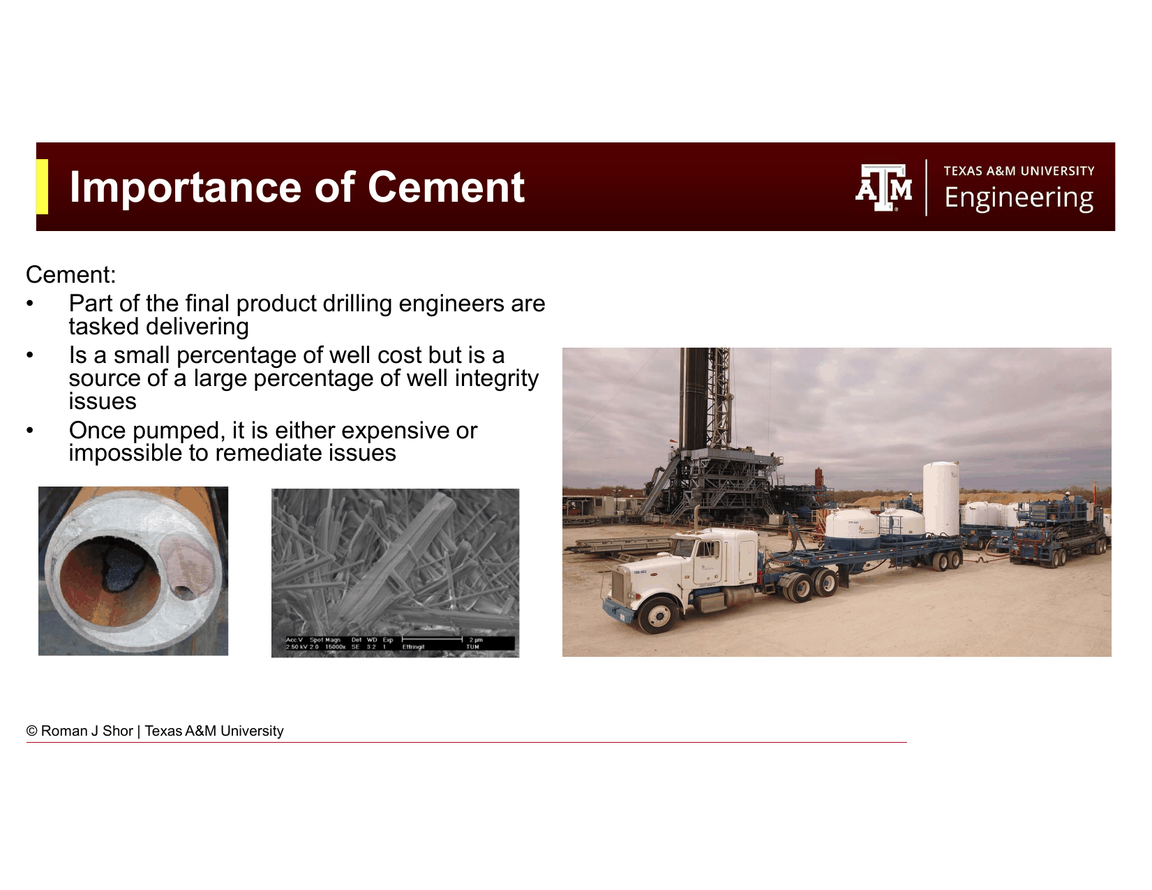
Fig. 249 Despite representing a small fraction of total well cost, cementing is responsible for a large percentage of well integrity issues throughout the life of the well.#
The fundamental objective of primary cementing is zonal isolation: preventing fluid migration between permeable zones of different pressure, and between those zones and the surface. Once primary cementing is complete, the annulus behind the casing is permanently sealed. If the cement job is poor, remediation (squeeze cementing) is expensive, uncertain, and often only partially successful. Getting the cement job right the first time is essential.
A secondary objective, equally important for safe well control, is demonstrating the strength of the cement at the casing shoe, this is the mechanical foundation for the leak-off test that defines the Maximum Allowable Annular Surface Pressure (MAASP) for the open-hole section below.
21.2 Cement Composition#
21.2.1 Portland Cement#
Portland cement is the base material for virtually all oilfield cementing. It is a calcium silicate material produced by heating limestone (calcium carbonate, CaCO₃) and clay (primarily silica, SiO₂, and alumina, Al₂O₃) to approximately 1,450°C in a rotary kiln, producing a clinker that is ground to a fine powder.
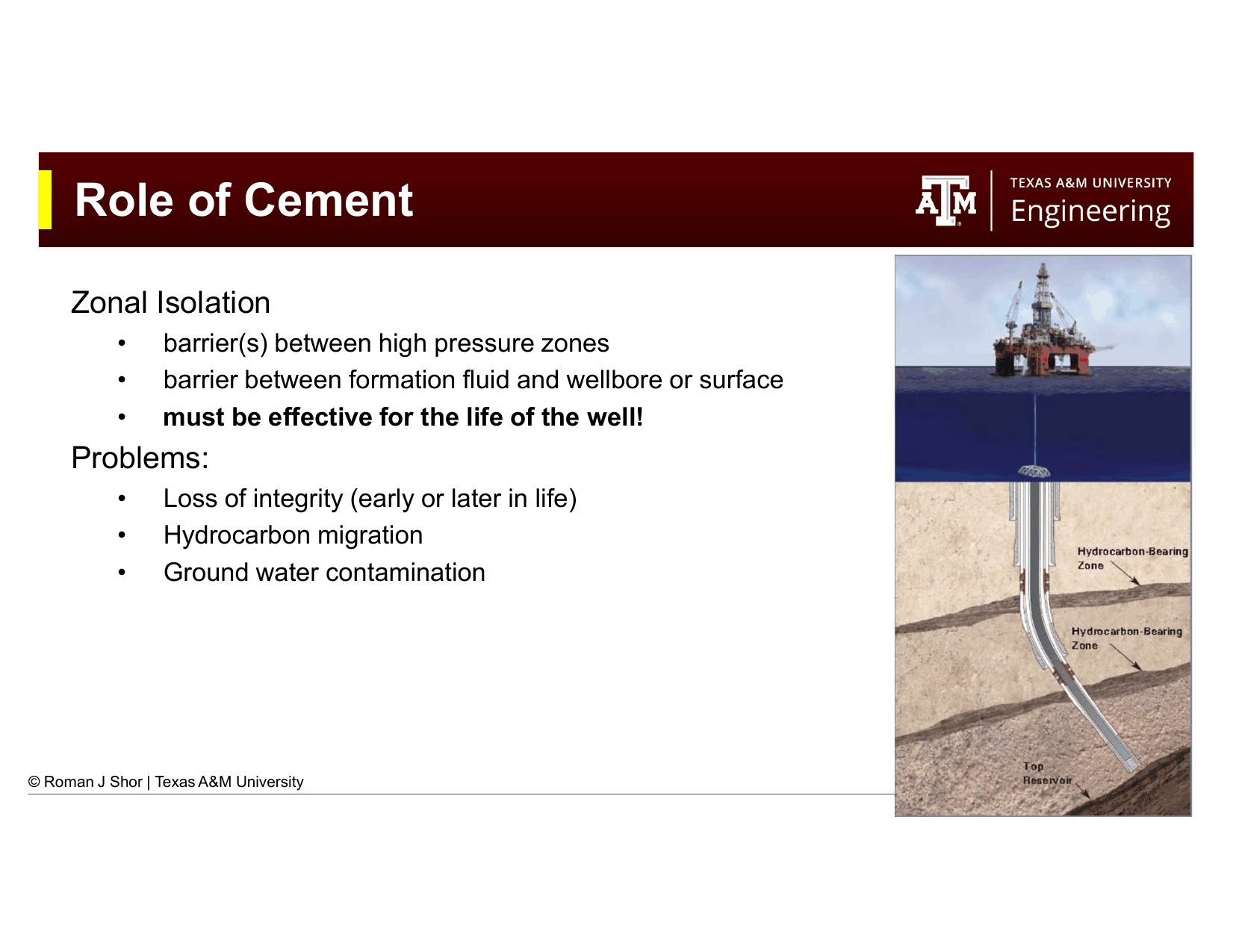
Fig. 250 Portland cement clinker composition: the four primary compounds and their role in hydration.#
The four primary compounds in Portland cement clinker, using cement chemistry shorthand notation:
Compound |
Full Name |
Symbol |
Typical Content |
Role in Hydration |
|---|---|---|---|---|
C₃S |
Tricalcium silicate |
Alite |
50–70% |
Early strength; primary heat source |
C₂S |
Dicalcium silicate |
Belite |
15–30% |
Late strength; slow hydration |
C₃A |
Tricalcium aluminate |
— |
5–12% |
Very rapid hydration; high heat; flash set risk |
C₄AF |
Tetracalcium aluminoferrite |
— |
5–12% |
Moderate hydration; color (gray) |
When Portland cement contacts water, each compound hydrates and forms calcium silicate hydrate (CSH), the gel phase that gives cement its strength, and calcium hydroxide (portlandite, Ca(OH)₂), which is water-soluble and can leach out over time. The hydration reactions are exothermic: they release significant heat, which is detectable with a temperature log immediately after the job.
21.2.2 Water Content#
Water is not just a reactant, it is also the carrier fluid for the cement slurry. The water:cement ratio affects:
Slurry density. More water = lower density slurry. For a standard neat (unmodified) Class G slurry, the water-to-cement ratio by weight is approximately 0.44 (or 5.0 gallons per sack of cement).
Free water. Excess water that does not chemically react forms free water, which separates from the slurry and leaves a water channel at the top of the cement column, a potential migration pathway. Free water is bad: it provides no strength and creates a defect in the cement bond.
Compressive strength. Too little water causes incomplete hydration (not all cement particles are hydrated, leaving dry unreacted powder). Too much water creates free water and a weak, porous matrix. The optimal water content for typical Class G is approximately 44–46% by weight.
Key Term
Free water is excess mixing water that does not react with the cement during hydration. It separates from the slurry (especially in inclined sections) and creates water channels that compromise zonal isolation. Free water is one of the primary causes of poor cement jobs.
21.2.3 API Cement Classes#
The American Petroleum Institute (API) standardizes oilfield cements into eight classes (A through H) based on their chemistry and the downhole conditions for which they are intended.
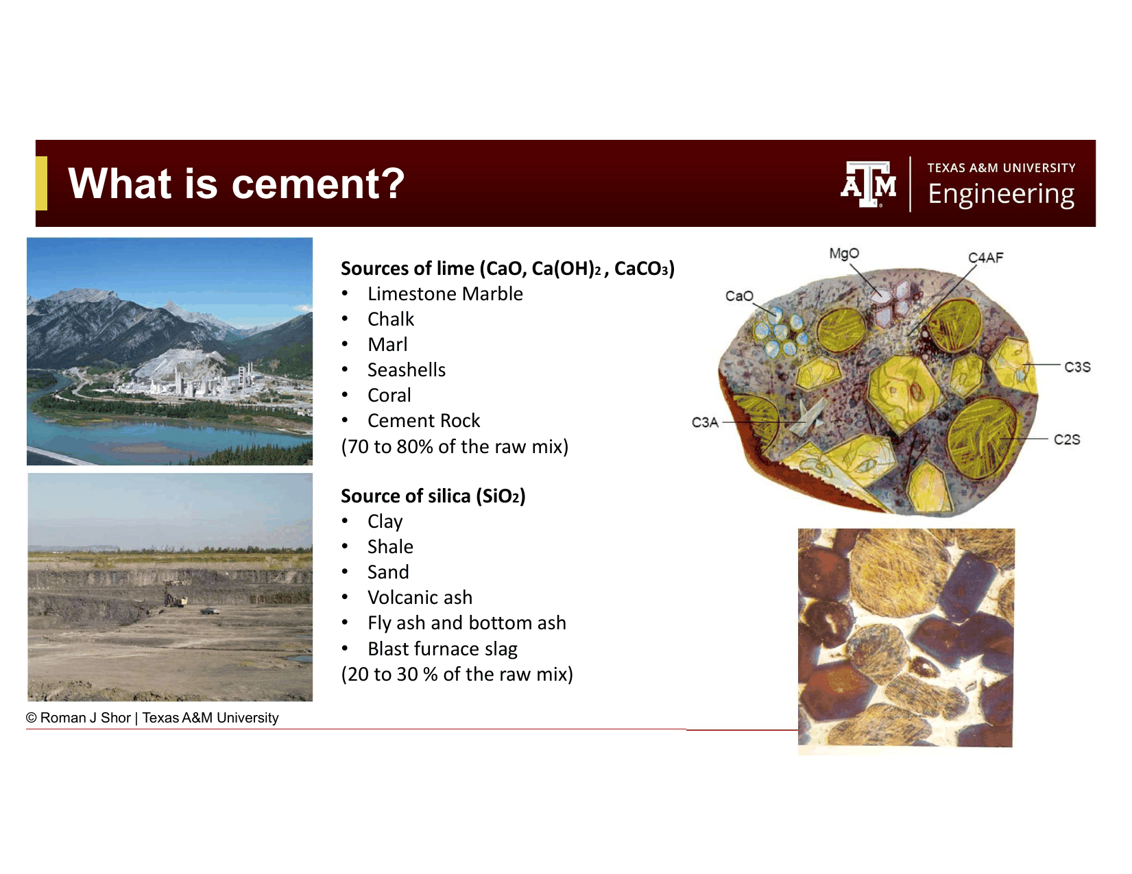
Fig. 251 API cement classifications. Class G and Class H are the industry standard for most cementing applications.#
Class |
Depth (ft) |
Temperature |
Notes |
|---|---|---|---|
A |
0–6,000 |
Mild |
Construction Portland; no additives; limited oilfield use |
B |
0–6,000 |
Mild |
Sulfate resistant; limited use |
C |
0–6,000 |
Mild |
High early strength; fast set; shallow wells |
D |
6,000–10,000 |
Moderate |
Retarded; for moderate temperatures |
E |
10,000–14,000 |
High |
More retarded; deep wells |
F |
10,000–16,000 |
Very high |
Most retarded; deepest wells |
G |
0–8,000 |
0–200°F |
Industry standard; can be modified with additives to any depth |
H |
0–8,000 |
0–200°F |
Industry standard; coarser grind than G; slightly different water requirement |
Class G and Class H are the overwhelming choice for most oilfield cementing jobs worldwide. They are “blank slate” cements: with no additives, they cover surface and intermediate casing depths. With accelerators, retarders, extenders, weighting agents, and specialty additives, Class G/H can be modified to handle virtually any downhole condition from the shallowest conductor to the deepest HP/HT production string.
The advantage of using a single base cement class is simplicity: mixing personnel, field lab equipment, and additive inventory are standardized. An engineer arriving on a new rig knows that if they can get G or H, they can cement almost any string with the right additive package.
21.3 Cement Setting Behavior#
21.3.1 The Hydration Sequence#
Cement hydration occurs in four stages:
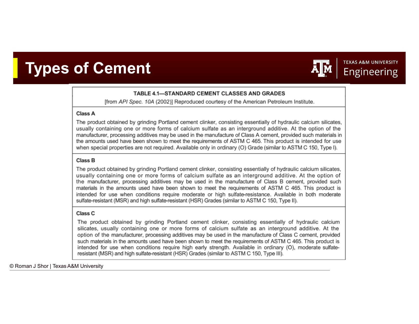
Fig. 252 The stages of Portland cement hydration: dissolution, induction, acceleration, and deceleration/diffusion.#
Dissolution (first minutes). Cement compounds dissolve at the surface of the particles and begin reacting with water. C₃A hydrates very rapidly, releasing a burst of heat. Gypsum (added to control C₃A reactivity) forms ettringite that coats the C₃A surface and slows the initial reaction.
Induction period (30 minutes to several hours). Also called the dormant period. The slurry is flowable; hydration proceeds slowly. This is the pumpable time window during which the cement must be mixed and placed downhole. The length of the induction period depends on cement class, temperature, and additives.
Acceleration (end of induction to several hours later). The protective layers on C₃A and C₃S surfaces break down, and hydration accelerates rapidly. The slurry begins to gel and build viscosity. Compressive strength begins to develop. The temperature rises sharply (exotherm peak). This is the transition period during which the cement cannot be pumped and is not yet a solid.
Deceleration / diffusion (hours to days). Water must diffuse through the thickening hydrate shell to reach unreacted cement core. Hydration slows. Strength continues to increase for weeks to months, eventually reaching final compressive strength.
Key Term
The thickening time of a cement slurry is the time (measured in Bearden Consistency Units on a pressurized consistometer) from mixing to when the slurry reaches a consistency of 100 BC units, beyond which it cannot practically be pumped. The job must be designed so that all placement is complete before the thickening time is reached.
21.3.2 Effect of Temperature#
Temperature is the most important variable in cement setting. Higher temperature accelerates all hydration reactions, shortening both the thickening time and the strength development time. The key implications:
Hot wells require retarded cement. At high bottomhole temperatures, Class G or H cement without additives may set before placement is complete. Retarders (typically lignosulfonates or organic acids) are added to extend the thickening time.
Cold wells require accelerated cement. In very cold conditions (deepwater wells at low seafloor temperatures), cement may take an unacceptably long time to set, delaying operations. Accelerators (calcium chloride, sodium silicate) speed up set.
Temperature gradient along the annulus. The same cement slurry sees the relatively colder wellbore temperature at the shoe and progressively warmer conditions along in the annulus. In a cement job, the coolest part of the wellbore sees the cement last (after it has been pumped down and around). This means the cement at the shoe is exposed to well-warmed conditions, while the cement at the top of the cement column may be in a much cooler formation.
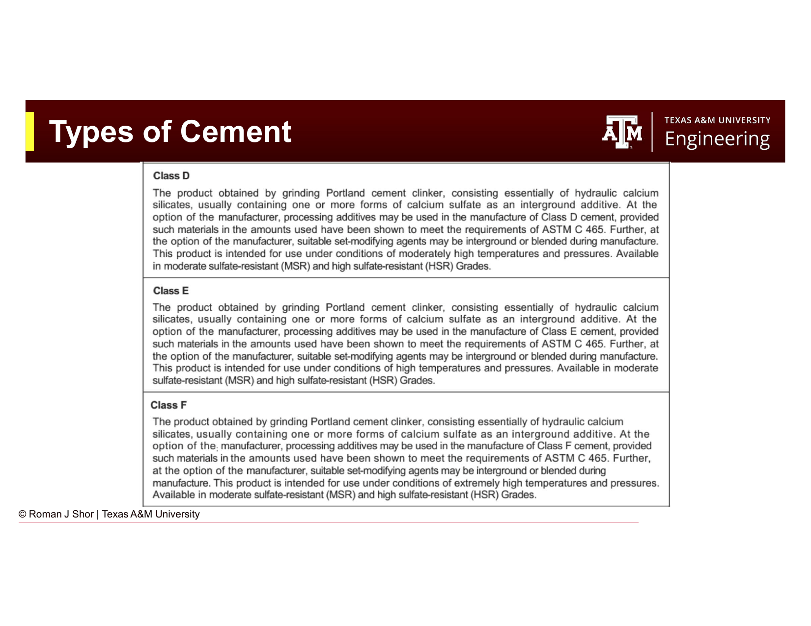
Fig. 253 Temperature and pressure effects on cement setting behavior. Higher temperature accelerates set; higher pressure tends to increase strength development rate.#
21.3.3 Effect of Downhole Pressure#
Hydrostatic pressure at depth generally increases compressive strength and reduces permeability of set cement. Class G/H cement performs well under typical wellbore pressure conditions. However, very high pressures (HP/HT wells) combined with high temperatures require specialty cement formulations or silica flour additions (to prevent strength retrogression, the weakening of cement at temperatures above ~230°F/110°C due to conversion of CSH to a weaker phase).
21.3.4 Contamination#
Cement contamination occurs when drilling mud mixes with the cement slurry during displacement. Contaminated cement has unpredictable and generally poor properties:
The set cement may be channeled with weak, porous zones
Compressive strength may be significantly reduced
Thickening time may be shortened (if mud components act as accelerators) or extended unpredictably
Preventing contamination is a primary objective of the cement job execution. A spacer fluid, a chemical wash or viscous spacer pumped ahead of the cement, is used to separate the mud from the cement and to clean mud residues off the casing and wellbore wall. A good spacer is chemically compatible with both the mud and the cement, and is turbulent (to scour the annulus).
21.4 Cement Equipment#
21.4.1 Float Shoe and Float Collar#
The float shoe is a special casing shoe run at the bottom of the casing string. It contains a check valve (float valve) that allows fluid to flow downward (out of the casing) but not upward (into the casing). The float valve serves two functions:
During running, the float shoe allows the mud inside the casing to exit out the bottom as the string descends, preventing the string from floating up.
After cementing, the float valve prevents the cement in the annulus from flowing back up into the casing (“U-tube backflow”), which would leave the shoe track empty of cement.
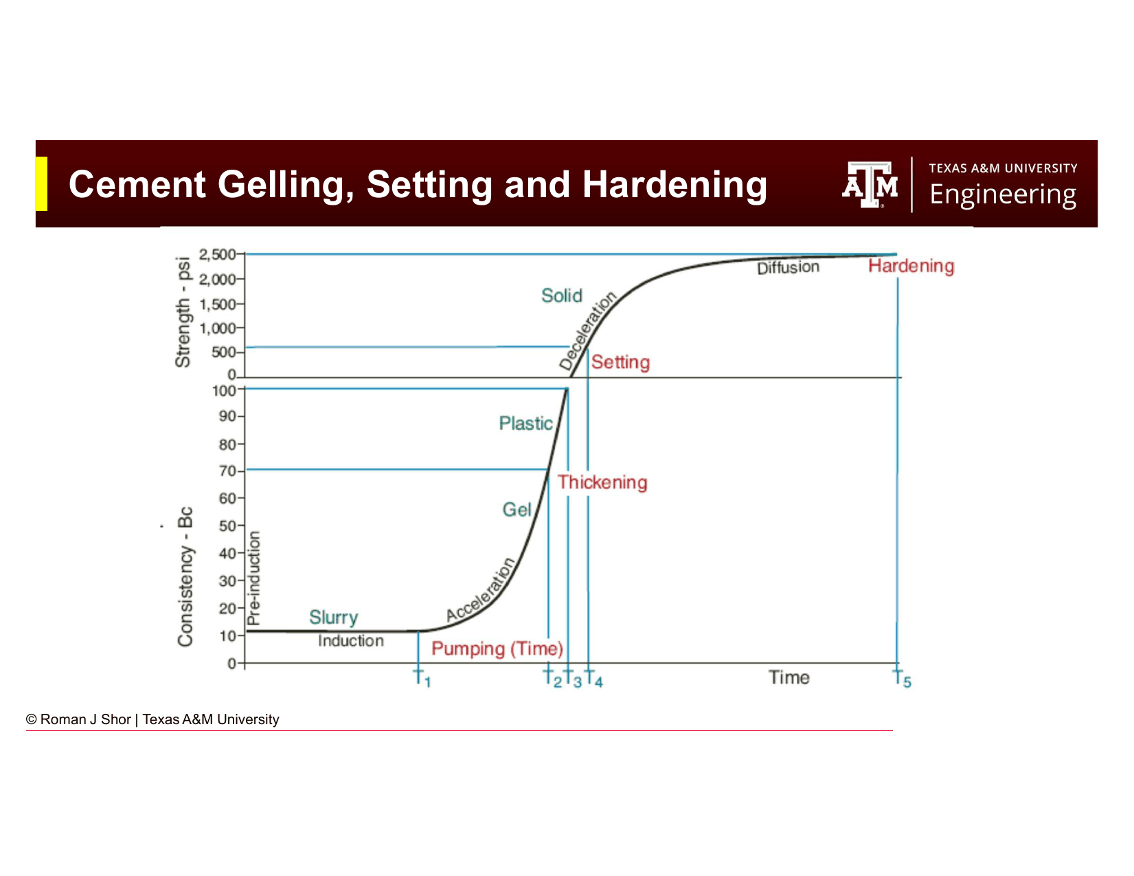
Fig. 254 Float shoe and float collar: the check valves that prevent backflow during cementing operations.#
The float collar is a similar check valve but is positioned one or two joints above the float shoe. The space between the float collar and the float shoe is the shoe track, the section of casing that will be drilled out after the cement job is complete. The shoe track is always filled with cement (it is inside the casing and below the float collar) and provides the mechanical foundation for the next drill-out.
When the bottom plug is bumped (see Section 21.6 for the typical cementing procedure), the differential pressure opens the float collar and allows cement to flow through. After displacement is complete, the float valve closes and holds the cement in place.
21.4.2 Cementing Plugs#
Cementing plugs are wiper plugs run inside the casing to separate the cement from both the mud in the casing above and below it. Without plugs, cement and mud intermix freely, causing contamination.
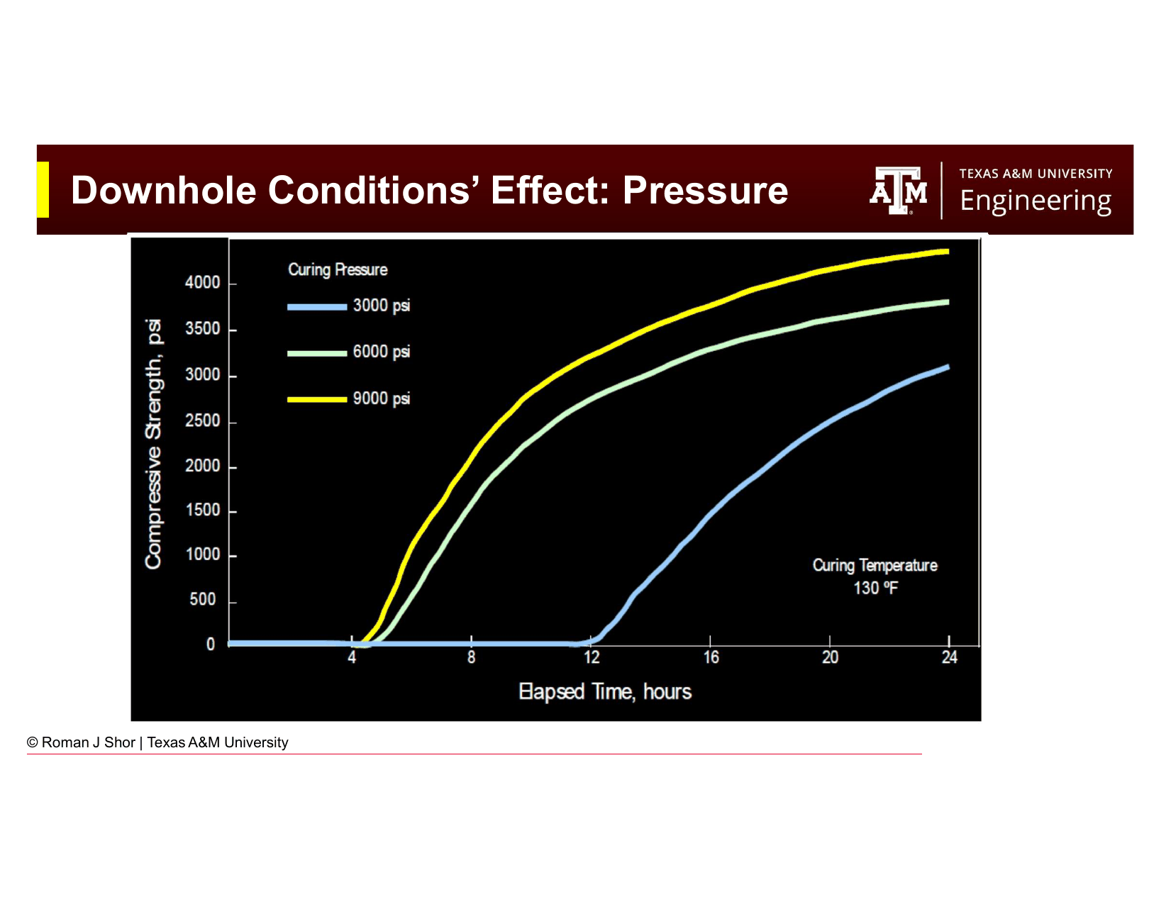
Fig. 255 Bottom and top cementing plugs (wiper plugs). The bottom plug separates mud from cement; the top plug pushes cement out of the casing into the annulus.#
Bottom plug: A rubber wiper plug launched just before the cement. It wipes mud off the casing ID wall as it travels down, keeping mud from contaminating the cement ahead of it. When it reaches the float collar, it seats and stops (bumps). Pressure is applied to rupture the plug’s diaphragm, allowing cement to flow through and down into the shoe track and up into the annulus.
Top plug: Launched after all the cement has been pumped. It has a solid core — no diaphragm. It wipes cement off the casing ID wall as it travels down. When it bumps on the seated bottom plug, displacement is complete. The bump is signaled by a pressure increase at surface, and pumping is stopped. This final position is called “plug bump.”
21.4.3 Stage Collars#
A stage collar (also called a multistage cementing collar or DV collar, differential valve) is a special casing joint with ports that can be opened downhole. Stage collars are used when the cement column cannot be placed in a single stage, for example, if the hydrostatic pressure of a full cement column would fracture the formation below, or if the zone to be cemented is so long that the annular friction pressure during placement would damage the formation.
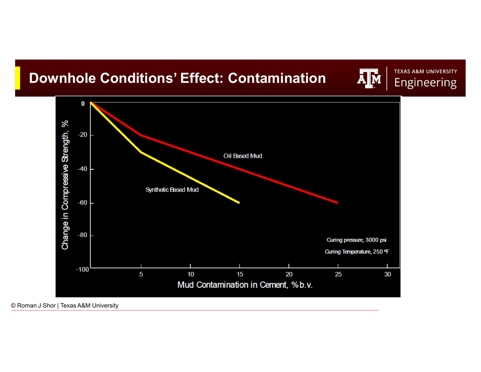
Fig. 256 A stage collar allows two-stage cementing, where the first cement stage covers the lower section and the second stage (pumped through the stage collar ports) covers the upper section.#
In two-stage cementing:
First stage: Cement the lower section of the annulus up to the stage collar depth, just as in a normal primary job.
Open the stage collar ports by dropping an opening plug from surface.
Second stage: Pump additional cement through the open stage collar ports to fill the upper annulus above.
Close the ports by dropping a closing plug.
21.4.4 Centralizers#
Centralizers keep the casing centered in the wellbore during running and cementing. Even in a vertical well, a casing string that is not centered (eccentric) will have a narrow side and a wide side in the annulus. Cement preferentially flows through the wide side (lower friction) and mud is trapped on the narrow side, exactly where good cement is needed most.
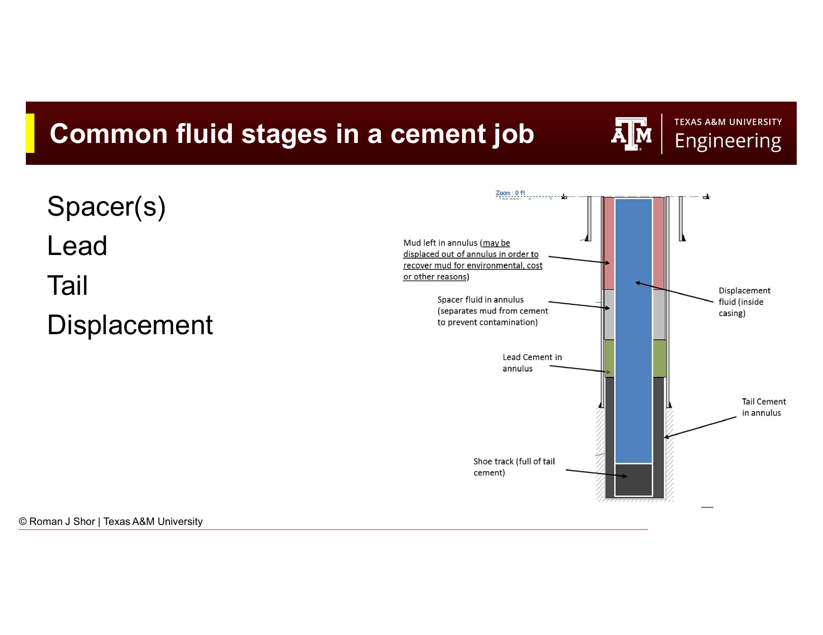
Fig. 257 Centralizer types: bow spring (flexible, for vertical wells) and solid body (rigid, for deviated and horizontal wells).#
Two types of centralizers:
Bow-spring centralizers: Made from spring steel bows that deflect to allow running through tight spots. They exert a restoring force that pushes the casing toward center. Best for near-vertical wells where the restoring force can act against gravity.
Solid body centralizers: A rigid sleeve around the casing with molded or machined fins. They maintain a defined standoff (distance between casing OD and borehole wall) regardless of lateral forces. Required in deviated and horizontal sections where bow springs would be compressed flat by the side force from the casing lying against the low side of the wellbore.
Key Term
Standoff is the minimum distance between the casing OD and the borehole wall, expressed as a percentage of the available annular clearance. Industry standard is ≥ 67% standoff (the casing is within the central third of the annulus). Good cement jobs require adequate standoff; below 50%, channeling is likely.
Centralizer spacing is calculated to maintain adequate standoff between centralizers given the casing weight per foot, wellbore deviation, and available clearance. In highly deviated wells, centralizers may be needed on every joint to maintain adequate standoff.
21.4.5 Casing Scratchers#
Casing scratchers (or wall scrapers) are wire or blade devices mounted on the casing string that scrape the borehole wall as the casing is reciprocated or rotated. Their purpose is to remove the mud filter cake from the borehole wall, improving bonding between cement and formation. They are used in combination with reciprocation or rotation of the casing during cement placement to maximize the area they contact.
21.5 Cement Fluid Stages#
A primary cement job pumps several fluid stages in sequence:
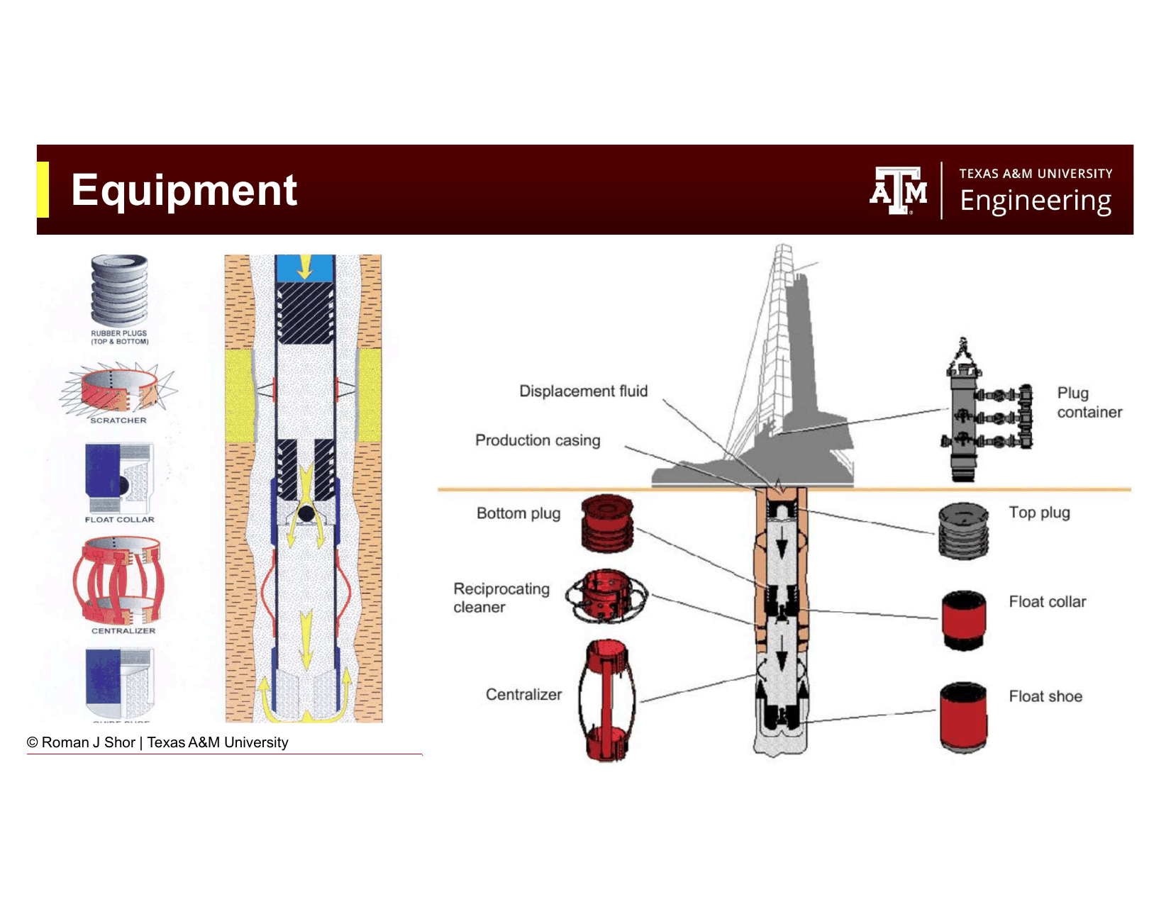
Fig. 258 The fluid stages in a primary cement job: spacer, lead cement, tail cement, and displacement fluid.#
Preflush / Spacer. A chemical wash (thin, water-like fluid for turbulent flow) or viscous spacer (thicker fluid for piston-like displacement) pumped ahead of the cement to separate the drilling mud from the cement and clean the casing ID and formation wall of mud residue. The spacer must be compatible with both the mud and the cement: if it gels or reacts with either, it creates a contaminated zone worse than no spacer at all.
Lead cement. A lighter cement slurry (lower density, often extended with additives) pumped first to fill the upper part of the annulus. Because the upper annulus is cooler and farther from the shoe, a lighter, more economical slurry is acceptable. Lead slurry typically covers the majority of the annular volume.
Tail cement. A heavier, higher-strength cement slurry pumped after the lead to fill the bottom of the annulus and the shoe track. The tail cement must provide the compressive strength needed for the shoe test and withstand the full pressure and mechanical loads at depth. It is typically neat or near-neat Class G/H.
Displacement fluid. Drilling mud (or water) pumped to displace the cement from inside the casing out through the float collar and into the annulus. The volume of displacement fluid equals the internal volume of the casing from the plug release collar to the float collar.
21.6 Primary Cementing: Step-by-Step Procedure#
The following describes the standard procedure for a primary cement job on a full-length casing string:
Before the job:
Calculate annular volume, shoe track volume, sacks of cement, mixing water, and displacement volume (Section 21.7)
Condition the mud: reduce viscosity and gel strengths to minimize gel-breaking pressure at the start of displacement
Rig up cement unit, mixing heads, and data recording system
Test all connections and verify float equipment functions with water
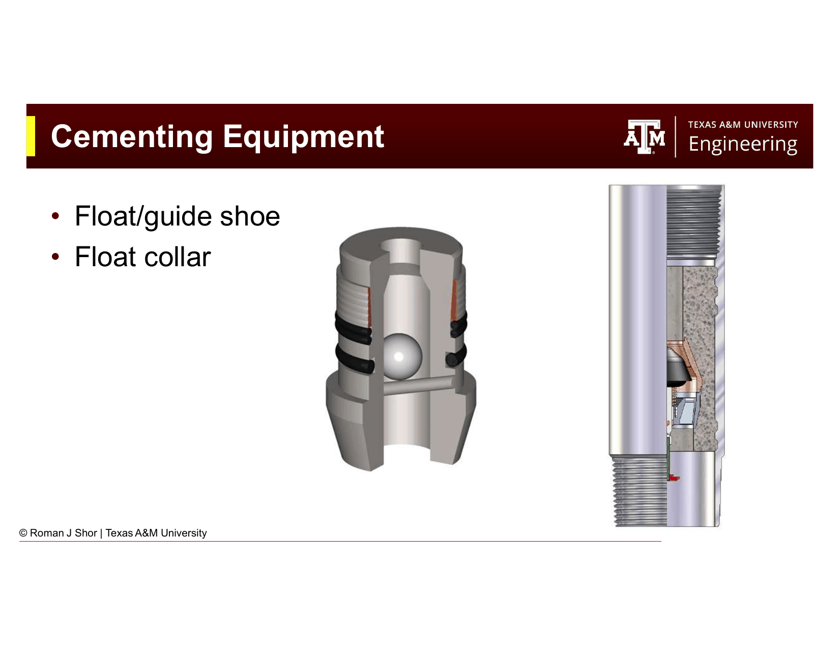
Fig. 259 Pre-job preparation and rig-up for primary cementing.#
Step 1: Run the casing string to depth.
Casing is run joint by joint with float shoe and float collar installed, centralizers placed on each joint at designed spacing, and scratchers (if used) installed. The string is circulated at least one full bottoms-up volume to condition the hole before cementing.
Step 2: Mix and pump the spacer.
The spacer is batch-mixed or mixed on-the-fly and pumped down the casing.
Step 3: Drop the bottom plug.
The bottom plug is released from the plug container at surface and falls to the fluid column in the casing.
Step 4: Mix and pump lead cement.
Lead cement is mixed on-the-fly using a continuous mixing unit and pumped behind the bottom plug.
Step 5: Mix and pump tail cement.
Tail cement follows the lead cement in one continuous pumping operation.
Step 6: Drop the top plug.
The top plug is released after all cement has been pumped. Displacement begins immediately.
Step 7: Displace with drilling mud.
Pump drilling mud to push the top plug (and cement below it) down to the float collar.
Step 8: Bump the plug.
When the top plug contacts the bottom plug (which is seated on the float collar), pressure at surface rises sharply. This is the plug bump, displacement is complete. Pumping stops.
Step 9: Check for backflow.
Bleed the standpipe pressure. If the float valves are functioning correctly, pressure will drop to zero and the cement will hold its position in the annulus. If backflow occurs, the float valve has failed.
Step 10: WOC (Wait on Cement).
No further operations are conducted until the cement has developed adequate compressive strength, typically 500–1,000 psi minimum, which takes 8–24 hours depending on the cement class, additives, and bottomhole temperature.
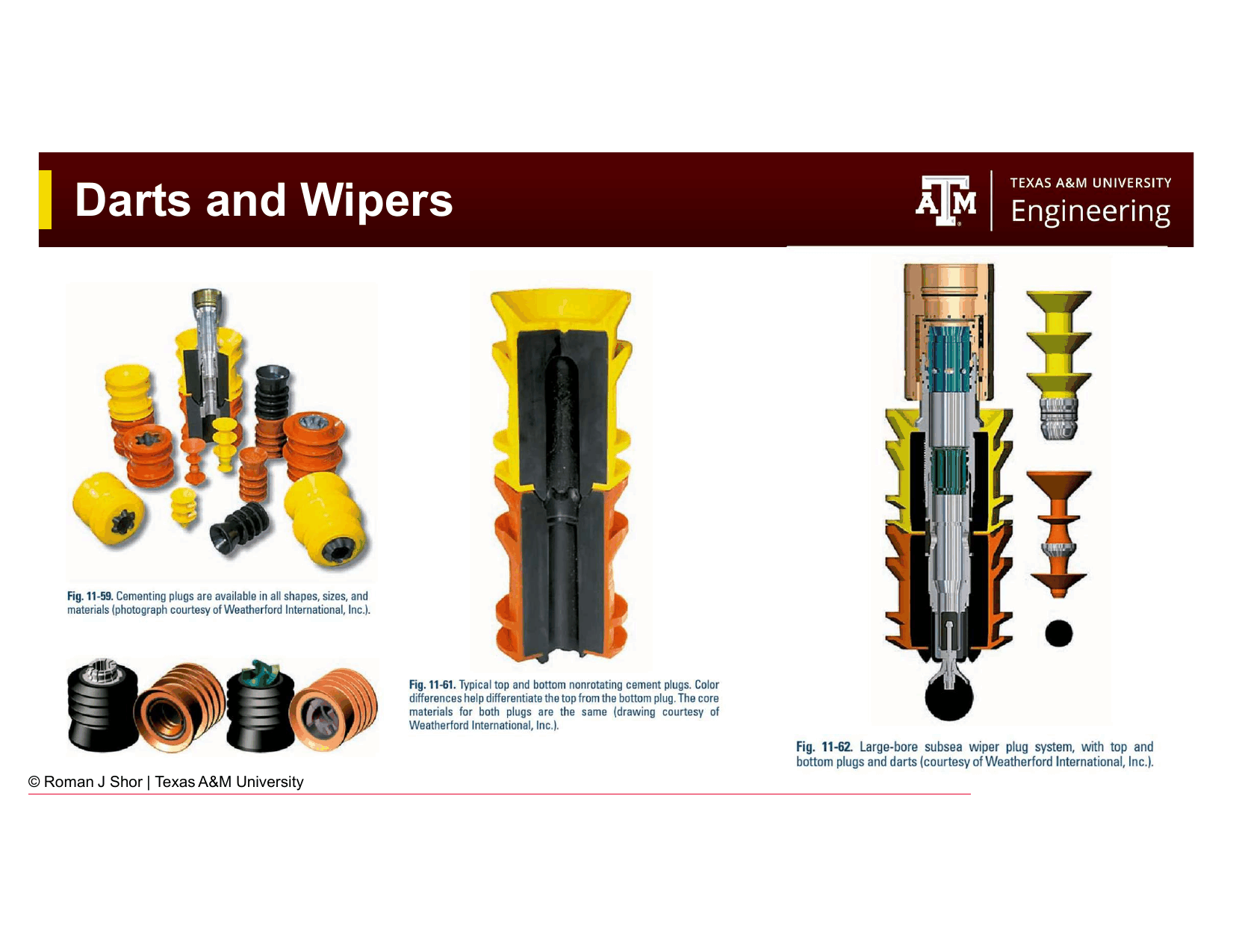
Fig. 260 Displacement phase: the top plug sweeps cement out of the casing into the annulus as drilling fluid is pumped behind it.#
21.7 Cementing Calculations#
21.7.1 Annular Volume#
The annular volume is the volume of space between the casing OD and the borehole wall (or outer casing ID) over the length of the cement column:
where the annular capacity \(C_\text{ann}\) (bbl/ft) is:
with diameters in inches and capacity in bbl/ft.
For a cased hole annulus (liner jobs or inner strings):
21.7.2 Shoe Track Volume#
The shoe track is the section of casing between the float collar and the float shoe. It is inside the casing and will be filled with tail cement. Its volume is the internal casing capacity times the shoe track length:
where the casing internal capacity \(C_\text{casing}\) (bbl/ft) is:
21.7.3 Sacks of Cement#
The number of sacks (94 lb/sack for a standard sack) is calculated from the total volume to be cemented and the yield of the cement slurry:
where \(Y\) is the slurry yield in ft³/sack (or bbl/sack). Yield is calculated from the slurry recipe:
For neat Class G cement mixed at 5.0 gal/sack:
Cement absolute volume: 94 lb / (3.14 × 8.33 lb/gal) = 3.59 gal
Water: 5.0 gal
Total: 8.59 gal = 8.59 / 7.48 = 1.15 ft³/sack
(The exact yield for Class G depends on the specific gravity of the cement, which is 3.14 for Class G.)
21.7.4 Mixing Water#
The total mixing water is:
where \(w_\text{gal/sack}\) is the water-to-cement ratio in gallons per sack (5.0 for standard neat Class G).
Converting to barrels: \(V_\text{water, bbl} = V_\text{water, gal} / 42\)
21.7.5 Displacement Volume#
The displacement volume is the internal volume of the casing from the plug release collar to the float collar:
where \(L_\text{casing}\) is the length of casing from surface to the float collar.
Converting capacity:
21.7.6 Worked Example#
Given:
7 in × 23 lb/ft casing set to 8,000 ft
Hole OD: 9 in
Cement bottom: 2,000 ft above shoe (cement column from 6,000 to 8,000 ft)
Shoe track: 80 ft (float collar at 7,920 ft)
Class H neat cement: density 15.5 ppg, yield = 1.22 ft³/sack, water = 5.49 gal/sack
Casing ID (7 in × 23 lb/ft): 6.366 in nominal
Step 1: Annular capacity
Note: This uses the nominal casing OD of 7 in and the hole diameter of 9 in.
Step 2: Annular volume (2,000 ft cement column)
Converting to ft³: \(62.16 \times 5.615 = 348.97 \text{ ft}^3\)
Step 3: Shoe track volume
Step 4: Total cement volume
Step 5: Number of sacks
Step 6: Mixing water
Step 7: Displacement volume
Length from plug release to float collar: 7,920 ft (using float collar at 7,920 ft)
Summary:
Sacks of cement: 301 sacks
Mixing water: 39 bbl (approximately 42 bbl including contingency)
Displacement volume: 312 bbl
21.8 Liner Cementing#
A liner cement job is fundamentally different from a full-string cement job because the liner does not extend to surface. A liner is typically run on drill pipe, so cement must be pumped through the drill pipe, down the liner, and up into the annulus between the liner OD and the previous casing ID to the liner hanger.
Fig. 261 Liner cementing: cement is displaced through the liner hanger and into the liner annulus. A liner wiper plug and a dart system replace the standard top plug arrangement.#
Key differences in liner cementing:
Drill pipe is used for displacement. Because the liner does not extend to surface, cement must be pumped down the drill pipe through the liner hanger into the liner. The drill pipe is pulled out after cementing.
Dart and wiper plug system. A dart (dropped from surface in the drill pipe) replaces the top plug. When the dart lands in a special seat (the drill pipe wiper plug), it sweeps the drill pipe clean and then the dart and plug together pass through the liner hanger and land on the liner wiper plug, which was launched from the liner hanger at the start of displacement.
Liner hanger/packer. The liner is hung off the previous casing with a liner hanger that also contains a packer element. The packer must be set before the cement job to prevent cement from flowing up inside the previous casing.
Liner cementing is mechanically more complex than full-string cementing and has more failure modes. Common issues include the liner hanger failing to set, the liner rotating when the packer is set, cement flowing up past the hanger, or the dart not landing properly. Careful rig-up, pre-job testing, and real-time pressure monitoring are essential.
21.9 Keys to a Good Cement Job#
Regardless of the job type (full string or liner), the same fundamental principles govern a good cement job:
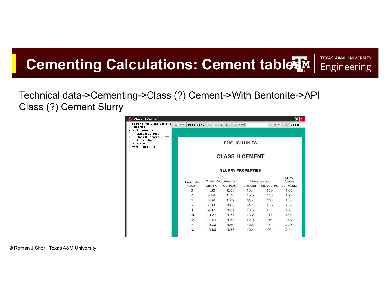
Fig. 262 The primary factors that determine cement job quality: mud conditioning, casing centralization, turbulent flow in the annulus, and compatible spacer.#
Centralize the casing. Adequate standoff (≥ 67%) is the single most important factor. A non-centralized string cannot achieve good circumferential cement coverage regardless of how carefully everything else is done.
Condition the mud. Reduce gel strength before cementing so that turbulent flow during displacement breaks up the gelled mud efficiently. Break all gels with at least one full bottoms-up circulation before cementing.
Use a good spacer. The spacer must be chemically compatible with both the mud and the cement, must maintain turbulent flow conditions in the annulus to scour mud residue, and must be of sufficient volume to create a clean interface.
Pump in turbulent flow. Turbulent flow in the annulus scours mud residue from the formation wall and casing OD, replacing it with cement. Laminar flow allows mud channels to persist. Design the job to achieve turbulent flow for the spacer and cement where possible.
Reciprocate or rotate the casing. Moving the casing during cement placement displaces the gelled mud and helps achieve better circumferential coverage. Even small movements help. This is particularly important in deviated wells.
Don’t leave free water. Ensure the slurry design minimizes free water, especially in deviated sections where free water collects on the high side of the wellbore and creates a water channel.
21.10 Cement Evaluation#
After the cement job is complete and WOC time has elapsed, the quality of the cement placement is evaluated. Three methods are commonly used, each with different timing and different information content.
21.10.1 Lift Pressure (Qualitative)#
The simplest evaluation is the lift pressure calculation. After the displacement is complete and the top plug is bumped, the pressure inside the casing above the top plug is the standpipe pressure at plug bump. If the cement in the annulus is providing a hydrostatic column, the casing should not move upward (lift off the slips or hanger).
Lift pressure is calculated as:
where the first term is the downward pressure from the cement column in the annulus and the second term is the upward hydrostatic pressure from the mud inside the casing.
If \(P_\text{lift} > 0\), the cement column is heavier than the mud inside and tends to push the casing up (liftoff risk). If \(P_\text{lift} < 0\), the casing tends to settle.
Lift pressure evaluation is qualitative: it tells you the gross hydrostatics of the cement column were as designed, but says nothing about whether channeling occurred, whether cement reached the target depth, or whether the bond is good.
21.10.2 Temperature Log#
Because cement hydration is exothermic, a temperature log run shortly after the cement job (within 4–12 hours of job completion, before the heat dissipates) shows a temperature anomaly where the cement is setting. The temperature increase is proportional to the mass of cement present.
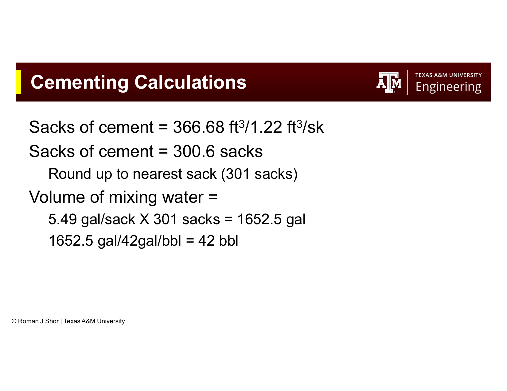
Fig. 263 Temperature log run after cement placement. The temperature anomaly identifies the top of cement and confirms cement reached its intended depth.#
What a temperature log can tell you:
The top of cement: cement generates heat above background; the top of the temperature anomaly is the top of the cement column
Whether the cement reached its intended depth
General indication of cement distribution
What a temperature log cannot tell you:
Channel distribution (the log is azimuthally averaged)
Compressive strength or seal quality
Bond quality between cement and casing or formation
Temperature logs are relatively inexpensive and provide useful information about cement placement depth. They must be run promptly, the temperature anomaly dissipates within 12–24 hours.
21.10.3 Cement Bond Log (CBL)#
The cement bond log (CBL) uses acoustic pulse-echo technology to evaluate the quality of the bond between the cement and the casing, and between the cement and the formation. A transmitter in the logging tool fires a high-frequency acoustic pulse; the amplitude of the resulting signal received at a nearby receiver is proportional to the amount of casing that is coupled (bonded) to cement. A casing string with excellent circumferential cement coverage attenuates the acoustic wave rapidly; a string with poor cement (channels, voids, or unbonded casing) transmits the acoustic wave with less attenuation.
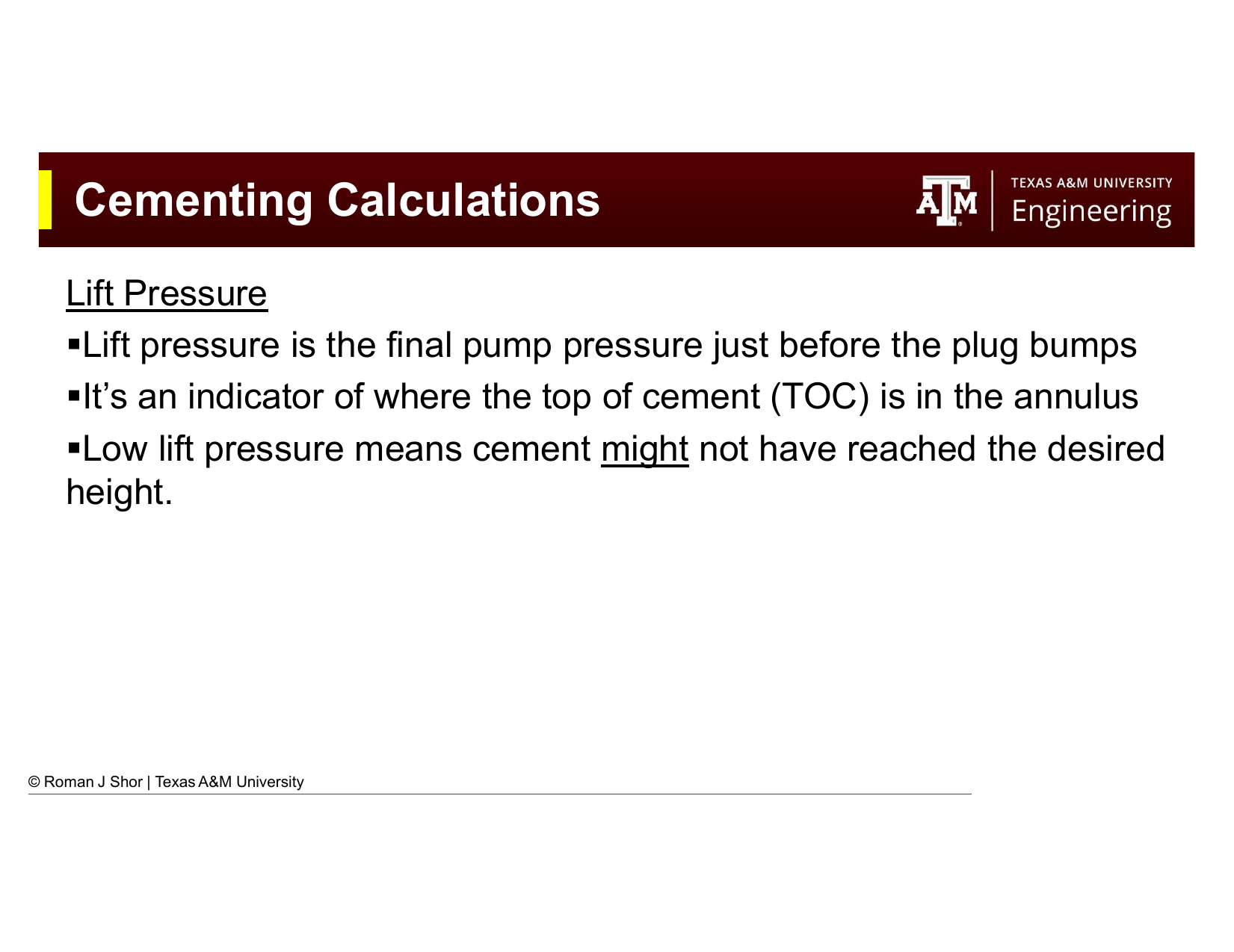
Fig. 264 Cement bond log (CBL) response: low amplitude (high attenuation) indicates good cement bonding; high amplitude (low attenuation) indicates poor bond or free pipe.#
Several types of CBL tools are available:
Standard CBL (two-receiver): Provides a single averaged measure of cement quality from one direction. Simple and fast, but cannot distinguish channeling on one side of the casing from overall poor cement.
Segmented bond tool (SBT) / Sector CBL: Eight or more receivers provide azimuthal (directional) cement quality evaluation, identifying channels by their circumferential location. This tool can find a small channel on one side of the casing that a standard CBL would average out.
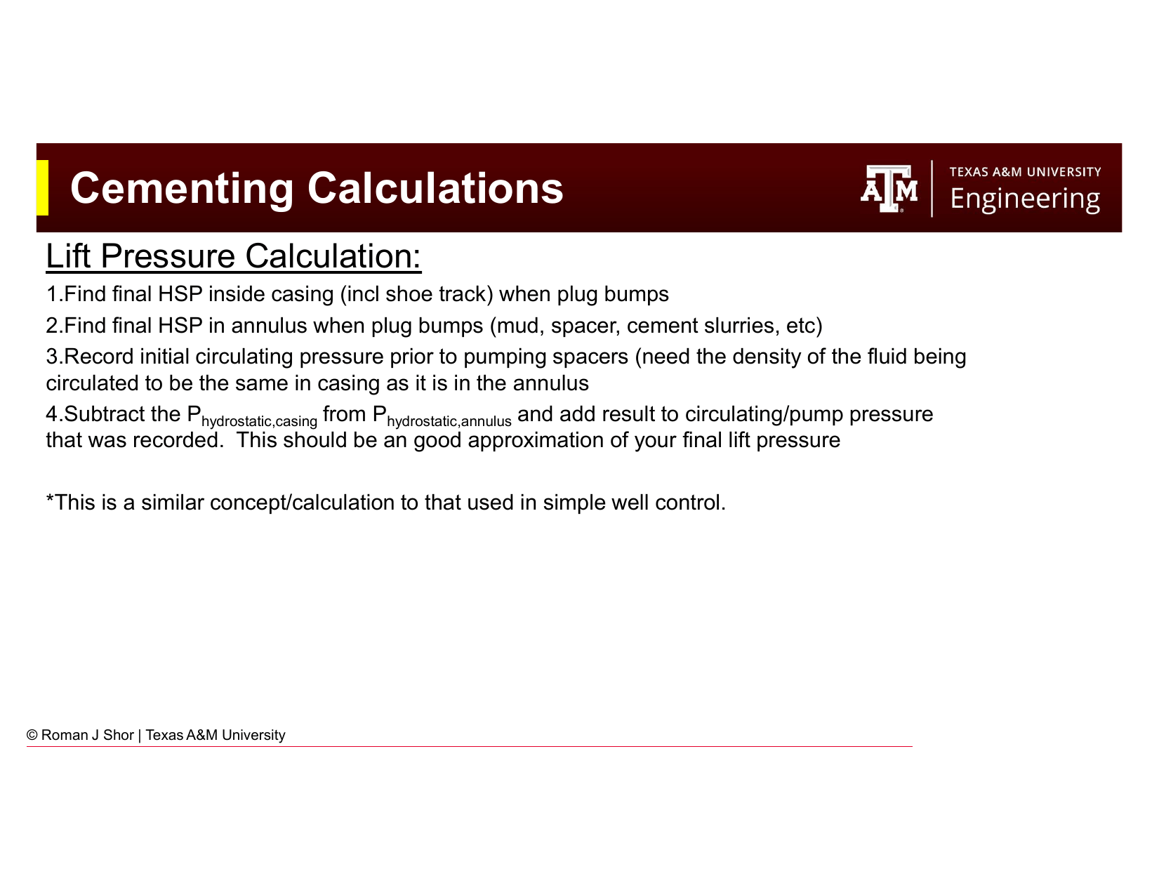
Fig. 265 Azimuthal (sector) cement bond tools provide a circumferential map of cement quality, showing the location and extent of channels.#
Interpreting a CBL:
High amplitude at the casing arrival (free pipe): The casing is not bonded to cement. Full attenuation is not occurring because the acoustic wave is traveling through free steel rather than attenuating into the cement matrix.
Low amplitude (full bond): The casing is bonded to a competent cement sheath. The acoustic energy is efficiently transferred from the casing into the cement and formation.
Intermediate amplitude (partial bond / microannulus): A thin gap between casing and cement (microannulus) may cause high CBL amplitude even when cement is present. Pressurizing the casing during logging can close a microannulus and confirm cement is present.
Limitations of CBL:
The tool can only be run after cement has fully set (typically 24–72 hours). Running too early gives unreliable results.
Microannulus can produce false “poor bond” readings.
The log is qualitative, not quantitative: experienced interpretation is required.
A good CBL does not guarantee zonal isolation if channels are smaller than the tool’s resolution.
Warning
A CBL log should not be accepted without qualified interpretation by a log analyst or experienced cementing engineer. The relationship between CBL amplitude and actual zone isolation quality is complex and depends on cement type, casing thickness, borehole fluid, and logging conditions.
Chapter Summary#
Cementing is the process that transforms a run casing string into a real pressure barrier. Portland cement (almost universally Class G or H) is mixed with water and pumped into the annulus, where it hydrates, an exothermic chemical reaction that converts the slurry from a pumpable fluid to a solid within hours. Temperature is the dominant variable: retarders extend the pumpable time for hot wells; accelerators speed up set for cold conditions.
The cementing equipment: float shoe, float collar, bottom and top plugs, stage collars, centralizers, and scratchers, each play a specific role in achieving clean, continuous cement placement. The key to a good job is casing centralization (≥ 67% standoff), good mud conditioning, a compatible spacer, and turbulent displacement flow.
Cementing calculations (annular volume, sacks of cement, mixing water, displacement volume) are straightforward volumetric calculations once the slurry yield is known. Cement evaluation progresses from qualitative (lift pressure), to semi-quantitative (temperature log), to detailed (cement bond log), with each method adding resolution at additional cost.
Key Equations Summary#
Quantity |
Formula |
|---|---|
Annular capacity (bbl/ft) |
\(C_\text{ann} = (d_\text{hole}^2 - d_\text{casing}^2) / 1029.4\) |
Casing internal capacity (bbl/ft) |
\(C_\text{cas} = d_\text{ID}^2 / 1029.4\) |
Annular volume (bbl) |
\(V_\text{ann} = C_\text{ann} \times L\) |
Number of sacks |
\(N = V_\text{total} (\text{ft}^3) / Y (\text{ft}^3/\text{sk})\) |
Mixing water (gal) |
\(V_w = w_\text{gal/sk} \times N_\text{sacks}\) |
Displacement volume (bbl) |
\(V_\text{disp} = C_\text{cas} \times L_\text{casing}\) |
Slurry density (ppg) |
\(\rho_s = (\text{mass of cement + mass of water}) / (\text{volume of cement + volume of water})\) |
Practice Problems#
21.1. A 9⅝ in × 40 lb/ft casing string (nominal ID = 8.835 in) is being set to 6,000 ft in a 12¼ in hole. The cement column will extend from the shoe at 6,000 ft to 1,000 ft above the shoe (covering 1,000 ft of annulus). The shoe track is 60 ft long (float collar at 5,940 ft).
Class G cement: density = 15.8 ppg, yield = 1.15 ft³/sk, water requirement = 5.0 gal/sk.
(a) Calculate the annular capacity (bbl/ft) between the casing OD and the 12¼ in hole.
(b) Calculate the annular volume of cement (bbl and ft³).
(c) Calculate the shoe track volume (bbl and ft³).
(d) Calculate total sacks of cement required.
(e) Calculate the total mixing water in gallons and barrels.
(f) Calculate the displacement volume (bbl) to bump the top plug.
21.2. A cement job uses lead cement (density 13.0 ppg, yield 1.55 ft³/sk, water 9.67 gal/sk) for the upper 4,000 ft of annulus and tail cement (density 15.8 ppg, yield 1.15 ft³/sk, water 5.0 gal/sk) for the lower 1,000 ft.
Annular capacity: 0.0450 bbl/ft (same throughout).
(a) Calculate the volume of each cement stage in ft³.
(b) Calculate the sacks of lead cement and tail cement separately.
(c) Calculate the mixing water for each stage.
(d) What is the total mixing water in barrels?
21.3. A temperature log run 8 hours after a cement job on a 13⅜ in surface casing shows a temperature anomaly from 500 ft to 1,800 ft. The casing was set at 2,000 ft and cement was designed to reach surface (0 ft).
(a) What depth does the temperature anomaly indicate as the top of cement?
(b) The top of cement is 500 ft, not at surface as designed. What does this tell you about the cement placement?
(c) List two possible causes for the cement not reaching surface.
(d) What remedial operation might be performed to fill the remaining 500 ft of uncemented annulus?
21.4. A CBL log shows:
From 0 to 4,000 ft: uniformly low amplitude (5–10% of free pipe amplitude)
From 4,000 to 5,500 ft: high amplitude (70–90% of free pipe amplitude) on one side (270° sector)
From 5,500 to 6,000 ft (casing shoe): low amplitude on all sides
(a) What does the low amplitude from 0–4,000 ft indicate?
(b) What does the high amplitude on one side from 4,000–5,500 ft indicate? Name one likely cause.
(c) Why might regulators require remediation of the 4,000–5,500 ft interval even if the total cement volume placed appears correct?
(d) The CBL was run 10 hours after the cement job on a deep, hot well. Is there a potential interpretation issue? Explain.
21.5. A casing string is being cemented with the following design:
Cement density: 15.5 ppg
Mud density inside casing: 12.0 ppg
Cement column height in annulus: 4,000 ft
Total casing length (surface to float collar): 9,920 ft
(a) Calculate the lift pressure: the net pressure difference between the cement hydrostatic and the mud hydrostatic that would tend to lift the casing.
where \(h_\text{mud\_ann} = 9920 - 4000 = 5920\) ft of mud in the annulus above the cement.
(b) Is the lift pressure positive (tending to lift the casing) or negative (net downward)? What does this mean operationally?