
Chapter 15 — Wellbore Geomechanics#
Learning Objectives#
By the end of this chapter, you should be able to:
Identify the types of borehole problems (breakout, washout, induced fractures, creep) and the formations in which each occurs.
Describe the three stresses acting at the wellbore wall (axial, radial, tangential) in cylindrical coordinates.
Explain what the Kirsch equations describe and why the wellbore wall is the critical location.
Calculate maximum and minimum hoop stress using the simplified Kirsch equations.
Apply the Mohr-Coulomb criterion to determine whether breakout will occur for a given mud weight.
Check the fracture criterion for a given mud weight and stress state.
Explain how breakout geometry determines whether a borehole stabilizes or collapses.
Write the maximum hoop stress expression for vertical and horizontal wells in a given stress regime.
15.1 Introduction#
Chapter 14 established how to describe and quantify in-situ stresses, effective stress, and rock failure. This chapter applies those concepts directly to the wellbore. When a circular hole is drilled through rock, the stress field around that hole is perturbed: the rock that was removed can no longer carry load, so the remaining formation must carry more. Whether this redistribution exceeds the rock’s strength determines whether the wellbore will be stable.
The analysis in this chapter answers the physics question: what are the stresses on the borehole wall, and will they cause failure? Chapter 16 answers the engineering question that follows: how do we keep the borehole stable, what mud weight is needed, and how is it selected in practice?
15.2 Types of Borehole Problems#
Several distinct failure modes can occur when drilling through different formations:
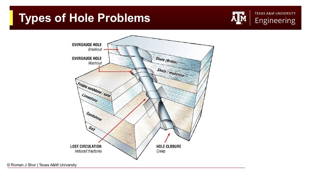
Fig. 191 Types of borehole problems encountered when drilling through different formations: breakout and washout (overgauge hole), induced fractures (lost circulation), and creep (hole closure).#
Overgauge hole — Breakout: In brittle formations (shale, competent rock), high in-situ stresses crush the borehole wall in two opposite zones, creating an enlarged, elliptical hole.
Overgauge hole — Washout: In weak or unconsolidated formations (friable sandstone, unconsolidated sand), the drilling fluid erodes the formation mechanically or hydraulically, producing a washed-out hole.
Lost circulation — Induced fractures: If mud weight is too high, the wellbore pressure fractures the formation and drilling fluid is lost into the induced fractures.
Hole closure — Creep: Salt and some soft shales are ductile materials that flow over time. A wellbore drilled through salt will begin closing almost immediately; the section must be cased quickly.
Field Sign of Breakout
At surface, breakout can manifest as unusually large or “boulder-sized” cuttings on the shale shaker — much larger than the normal chip-size cuttings produced by the drill bit. If you see these, the wellbore wall is collapsing. Breakout can also manifest as more splinter or shard like cuttings, the size of coins. This is an indication of spalling and the formation is failing in compression.
15.3 Stresses at the Wellbore Wall#
When analyzing stability, we switch from Cartesian (x-y-z) to cylindrical coordinates centered on the wellbore axis. At any point on the borehole wall, three orthogonal stresses act:
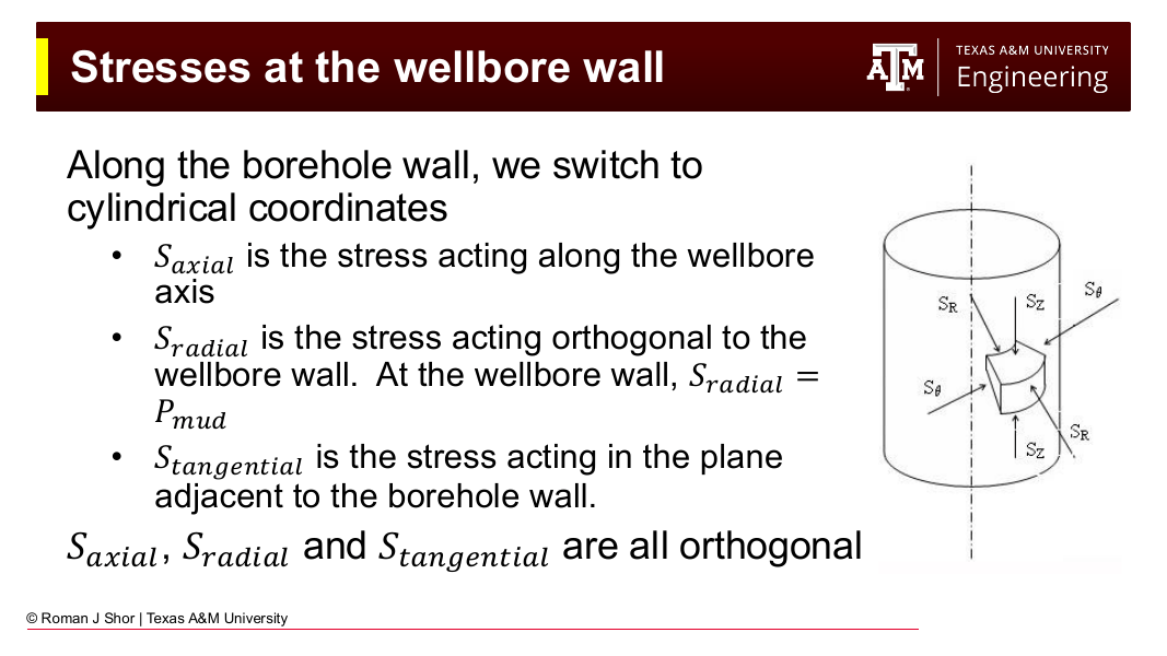
Fig. 192 Cylindrical coordinate system for wellbore stress analysis: \(S_r\) (radial), \(S_\theta\) (tangential/hoop), and \(S_z\) (axial) are mutually orthogonal at every point on the borehole wall.#
Axial stress (\(S_z\) or \(S_{axial}\)): Acts along the wellbore axis. For a vertical well, this equals the overburden stress \(S_v\). For a deviated well, it is a combination of \(S_v\) and the horizontal stresses.
Radial stress (\(S_r\) or \(S_{radial}\)): Acts perpendicular to the wellbore wall, pointing outward from the axis. At the wellbore wall itself, this equals the mud pressure \(P_m\) — the drilling fluid exerts a radial support pressure.
Tangential stress (\(S_\theta\) or \(S_{tangential}\)): Also called the hoop stress, this acts along the circumference of the wellbore wall. It varies around the circumference depending on the orientation of the far-field geologic stresses.
These three stresses are the \(S_1\), \(S_2\), and \(S_3\) for the near-wellbore problem: we use them in the Mohr circle to assess failure.
15.4 The Kirsch Equations#
The Kirsch equations describe how stresses vary with distance from the wellbore center. For a vertical well in a biaxial stress field (\(S_H\) and \(S_h\)), the stresses at distance a from the wellbore center (where the wellbore radius is \(r_w\)) are:
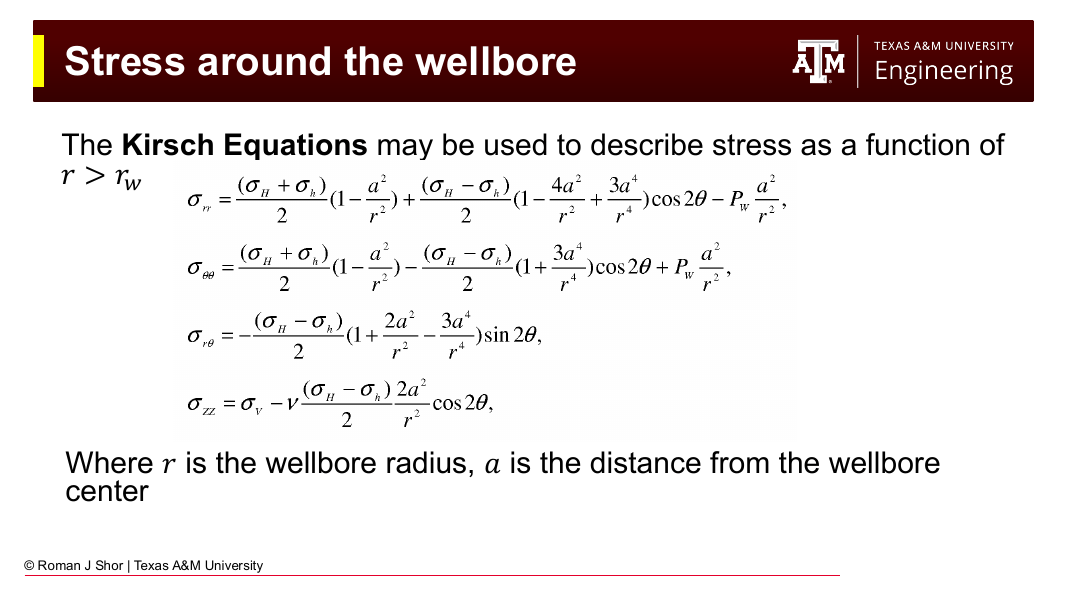
Fig. 193 Stress as a function of distance from the wellbore, from the Kirsch equations. The perturbation is strongest at the wellbore wall and decays to the far-field stress state within a few wellbore radii.#
These equations are not required for routine calculations. Their key message is: stresses are most perturbed at the wellbore wall and return to the far-field geologic values several wellbore radii away. We are primarily concerned with the engineering problem at the wellbore wall, where a = rw.
15.5 Simplified Kirsch Equations at the Wellbore Wall#
At the wellbore wall (\(a = r_w\)), the Kirsch equations simplify considerably:
where:
\(P_m\) = mud pressure (hydrostatic pressure of the drilling fluid column)
\(S_H\) = maximum horizontal stress
\(S_h\) = minimum horizontal stress
\(\theta\) = angle measured from the direction of \(S_H\)
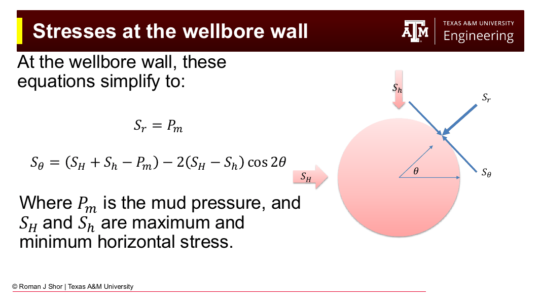
Fig. 194 At the wellbore wall the Kirsch equations simplify to \(S_r = P_m\) and \(S_\theta = (S_H + S_h − P_m) − 2(S_H − S_h)cos 2\theta\), where \(\theta\) is measured from the \(S_H\) direction.#
The radial stress \(S_r = P_m\) is uniform around the wellbore: the mud supports the wall equally in all directions. The hoop stress \(S_\theta\) varies sinusoidally around the circumference, with maximum and minimum values at specific locations.
15.6 Maximum and Minimum Hoop Stress#
The hoop stress achieves its extreme values at the directions of the principal horizontal stresses:
Maximum hoop stress at \(\theta = 90^o\) (in the direction of minimum horizontal stress \(S_h\)):
Minimum hoop stress at \(\theta = 0^o\) (in the direction of maximum horizontal stress \(S_H\)):
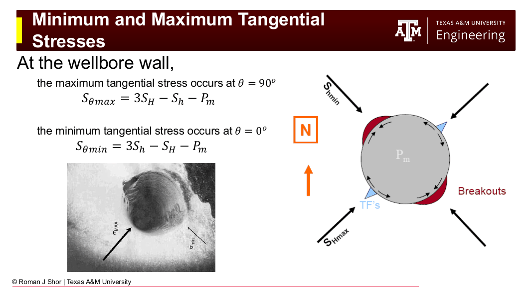
Fig. 195 Breakouts (compressive failure, red) form in the direction of Shmin, where hoop stress is maximum; drilling-induced tensile fractures (TFs, blue) form 90° away in the direction of \(S_{Hmax}\), where hoop stress is minimum. The inset photograph shows a laboratory breakout aligned with the applied stresses.#
The physical interpretation is intuitive: the maximum horizontal stress \(S_H\) acts like a crushing force on the wellbore from two sides. Where it “squeezes” hardest (opposite its own direction, i.e., in the \(S_h\) direction), the hoop stress is maximum and breakout may occur. Where the wellbore wall is stretched (in the \(S_H\) direction), the hoop stress is minimum and fracturing may initiate.
Breakout Direction as a Stress Indicator
Because breakout always occurs orthogonal to \(S_{Hmax}\), borehole image logs that show breakout direction are a valuable tool for mapping the orientation of the horizontal stress field. The direction of breakout = direction of \(S_{hmin}\).
15.7 Borehole Instability: Breakout#
Breakout is compressive failure of the wellbore wall. It occurs in the direction of maximum hoop stress: where the formation is being “crushed” by the concentrated stress around the hole.
The failure criterion uses the Mohr-Coulomb approach from Chapter 14. At the location of maximum hoop stress, the two principal effective stresses on the wellbore wall are:
Maximum effective stress (\(\sigma_1\)): The effective hoop stress at the breakout location
Minimum effective stress (\(\sigma_3\)): The effective radial stress (mud support minus pore pressure)
With \(\sigma_1\) and \(\sigma_3\) determined, the Mohr circle is constructed and the failure check is performed:
Calculate \(\sigma_n\) and \(\tau\) at the failure point using the Mohr circle equations (with \(\tau\) from the friction angle)
Compare to the failure criterion: if \(\tau > C + \sigma_n \cdot tan(\theta)\) → breakout occurs
Note the role of mud weight: increasing Pm decreases \(\sigma_1\) (reduces the hoop stress) and increases \(\sigma_3\) (provides more radial support). Both effects move the Mohr circle away from the failure envelope — a higher mud weight prevents breakout.
15.8 Borehole Instability: Induced Fractures#
Tensile fracture occurs at the location of minimum hoop stress — in the direction of maximum horizontal stress \(S_H\). The criterion is much simpler than the breakout check:
For a wellbore with pre-existing fractures (the common case):
For an intact wellbore:
Since cohesion \(C\) is positive, it is harder to fracture an intact rock than to reopen an existing fracture. In practice, most wellbores are treated as fractured because natural fractures and pre-existing drilling-induced fractures are ubiquitous.
Important consequence: Once a fracture is created, it is much easier to reopen it than to initiate a new one. The opening pressure for a pre-existing fracture is lower than the original fracture initiation pressure. This is why exceeding the fracture gradient even once can permanently reduce the upper bound of the drilling window.
The mud weight controls both bounds: High mud weight → prevents breakout but risks fracturing. Low mud weight → prevents fracturing but risks breakout (and kicks). When \(S_{Hmax}\) and \(S_{hmin}\) are very different (high stress anisotropy), the drilling window may be narrow or even non-existent, and the engineer must choose the “least bad” option.
15.9 Borehole Breakout Stability#
Not all breakout leads to wellbore collapse. The geometry of the breakout zone determines whether it stabilizes or continues to grow.
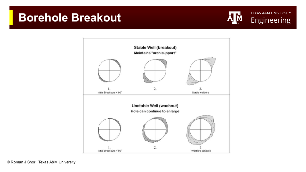
Fig. 196 Breakout stability. Top: initial breakouts < 90° maintain “arch support” and the wellbore stabilizes in an overgauge but stable shape. Bottom: initial breakouts > 90° lose arch support and the hole continues to enlarge toward collapse.#
By analogy with the arch in a cathedral: the intact portion of the borehole wall acts as a “flying buttress” that carries the concentrated stress around the breakout zone. As long as the breakout angle (the angular extent of failed rock) is less than about 90° on each side, the remaining intact arc is sufficient to maintain structural integrity — the hole is overgauge but stable.
If the breakout angle exceeds 90°, the arch support is insufficient and the breakout grows progressively, eventually leading to wellbore collapse. The solution is to circulate out debris and increase mud weight while drilling.
Detection: A multi-arm caliper log measures borehole diameter in multiple directions. An elliptical cross-section indicates directional breakout. A borehole image log (resistivity or acoustic) shows breakout zones as wide dark bands 180° apart, with narrow dark bands (induced fractures) 90° away.
15.10 Effect of Well Orientation#
The stresses acting on the hoop depend on which in-situ stresses are “perpendicular” to the wellbore axis. As well inclination changes, the relevant stress combinations change.
Vertical Well#
The wellbore is parallel to \(S_v\). The two horizontal stresses (\(S_H\) and \(S_h\)) act perpendicular to the wellbore axis and appear in the hoop stress equations:
Horizontal Wells (Normal Faulting Regime)#
In normal faulting, \(S_v > S_H > S_h\). The overburden \(S_v\) is the largest stress.
Horizontal well drilled parallel to \(S_{hmin}\) (the wellbore axis points in the \(S_{hmin}\) direction):
The two stresses perpendicular to the wellbore are \(S_v\) and \(S_H\):
Horizontal well drilled parallel to \(S_{Hmax}\) (the wellbore axis points in the SHmax direction):
The two stresses perpendicular to the wellbore are \(S_v\) and \(S_h\):
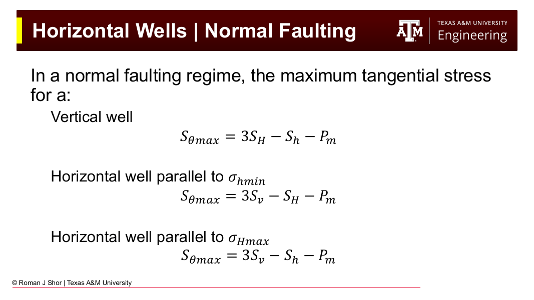
Fig. 197 Maximum hoop stress expressions in a normal faulting regime for a vertical well and for horizontal wells drilled parallel to \(S_{hmin}\) and parallel to \(S_{Hmax}\). The stresses perpendicular to the wellbore axis determine the hoop stress.#
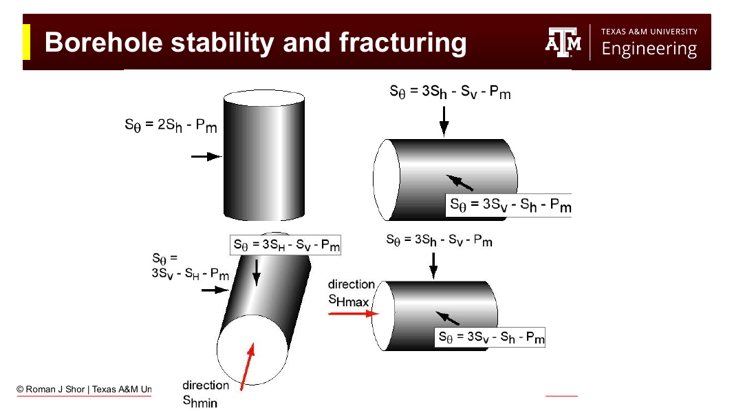
Fig. 198 Hoop stress expressions for wellbores of different orientations relative to the principal stress directions. Rotating the wellbore axis swaps which far-field stresses appear in the \(3S − S − P_m\) combination.#
Since \(S_v\) is the largest stress in normal faulting, placing it in the “3S” position (as happens for horizontal wells) produces a much larger maximum hoop stress than a vertical well — which is why horizontal wells in normal faulting environments typically require higher mud weights for stability.
Arbitrary Orientations and Lower Hemisphere Plots#
For arbitrary well orientations (any inclination and azimuth), the stress tensor must be rotated into the wellbore coordinate frame, and the hoop stress no longer has a simple closed form — software performs the computation. The results are conveniently displayed on a lower hemisphere stereonet plot: the center of the plot represents a vertical well, the outer edge represents horizontal wells in each azimuth, and color contours show the required mud weight for every possible drilling direction. These plots immediately reveal the “easy” and “hard” drilling directions given the local stress field.
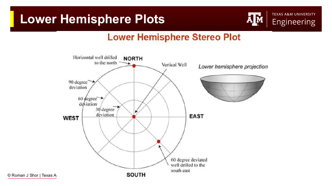
Fig. 199 The lower hemisphere stereo plot. Every point represents a well orientation: the center is a vertical well, the rim is horizontal, and the compass direction gives the well azimuth. Contouring required mud weight on this projection maps the stability of every possible drilling direction.#
15.11 Worked Example: Breakout and Fracture Analysis#
Problem: A vertical well is being drilled in a reverse faulting regime at 10,000 ft TVD. The following information is available:
Pore pressure: Pp = 10 ppg equivalent
Overburden stress: Sv = 1.0 psi/ft
Maximum horizontal stress: SH = 11,000 psi
Minimum horizontal stress: Sh = 10,500 psi
Rock strength: C = 2,000 psi, θ = 30°
Selected mud weight: Pm = 11 ppg
Step 1: Convert pore pressure and mud pressure to psi
Pore pressure: $\(P_p = 10 \text{ ppg} \times 0.052 \times 10{,}000 \text{ ft} = 5{,}200 \text{ psi}\)$
Mud pressure: $\(P_m = 11 \text{ ppg} \times 0.052 \times 10{,}000 \text{ ft} = 5{,}720 \text{ psi}\)$
Since Pm (5,720) > Pp (5,200): primary well control is established.
Step 2: Calculate maximum hoop stress (breakout check)
For a vertical well:
Step 3: Calculate effective stresses
Step 4: Find the failure point on the Mohr circle
Using φ = (90° − θ)/2 = (90° − 30°)/2 = 30°, so 2φ = 60°:
Step 5: Check against Mohr-Coulomb failure criterion
Comparison: τ = 4,789 psi > 3,896 psi → Breakout occurs at this mud weight
To prevent breakout, the mud weight must be increased until the effective stress circle falls below the failure envelope. (Chapter 16 shows how to solve for that minimum mud weight directly.)
Step 6: Check for induced fractures
The effective minimum hoop stress:
Since σθ,min = +9,580 psi >> 0, the wellbore wall is in compression at the fracture-prone location. No fracturing at this mud weight.
Summary: At 11 ppg mud weight, breakout is predicted but fracturing is not. The engineer must increase mud weight to prevent breakout; the upper limit is constrained by the fracture gradient.
Practice Problems#
Problem 15.1 — Stability Check in Normal Faulting
A vertical well is drilled at 8,000 ft TVD in a normal faulting regime. The geologist provides:
Pore pressure: Pp = 8.5 ppg
Overburden: Sv = 0.90 psi/ft
Maximum horizontal stress: SH = 5,000 psi
Minimum horizontal stress: Sh = 4,200 psi
Rock strength: C = 1,000 psi, θ = 30°
Selected mud weight: Pm = 9.0 ppg
(a) Verify the stress ordering for normal faulting. (b) Is primary well control established? (c) Does breakout occur? (d) Do induced fractures form?
Solution
(a) Stress ordering
\(S_v = 0.90 \times 8{,}000 = 7{,}200\) psi
\(S_v = 7{,}200 > S_H = 5{,}000 > S_h = 4{,}200\) psi ✓ Normal faulting confirmed.
(b) Primary well control
\(P_p = 8.5 \times 0.052 \times 8{,}000 = 3{,}536\) psi
\(P_m = 9.0 \times 0.052 \times 8{,}000 = 3{,}744\) psi
\(P_m = 3{,}744 > P_p = 3{,}536\) psi ✓ Primary well control established.
(c) Breakout check
\(\tau = 1{,}434 < 1{,}598\) psi → No breakout. The well is stable in compression.
(d) Fracture check
No induced fractures. The wellbore wall is in compression everywhere. At 9.0 ppg this well is fully stable — in this low-contrast normal-faulting environment, pore pressure is the only active lower bound.
Problem 15.2 — Breakout and Fracture in a Strike-Slip Regime
A vertical well is drilled at 10,000 ft TVD in a strike-slip regime with high stress contrast:
Pore pressure: Pp = 10.0 ppg
Overburden: Sv = 1.0 psi/ft
Maximum horizontal stress: SH = 12,000 psi
Minimum horizontal stress: Sh = 8,000 psi
Rock strength: C = 1,500 psi, θ = 30°
Selected mud weight: Pm = 10.5 ppg
(a) Verify the stress ordering for strike-slip faulting. (b) Does breakout occur at 10.5 ppg? (c) Do induced fractures form at 10.5 ppg? (d) What action should the engineer take, and why is strike-slip more challenging than normal faulting?
Solution
(a) Stress ordering
\(S_v = 1.0 \times 10{,}000 = 10{,}000\) psi
\(S_H = 12{,}000 > S_v = 10{,}000 > S_h = 8{,}000\) psi ✓ Strike-slip confirmed.
\(P_p = 10.0 \times 0.052 \times 10{,}000 = 5{,}200\) psi
\(P_m = 10.5 \times 0.052 \times 10{,}000 = 5{,}460\) psi
(b) Breakout check
\(\tau = 7{,}395 \gg 4{,}114\) psi → Breakout occurs. The Mohr circle greatly exceeds the failure envelope.
(c) Fracture check
No induced fractures at 10.5 ppg. The wellbore wall remains in compression everywhere, including at the SH direction.
(d) Engineering action and comparison
Increase mud weight. The strike-slip regime has a stress difference of \(S_H - S_h = 4{,}000\) psi — much larger than the normal-faulting example in Problem 15.1 (only 800 psi). This large anisotropy concentrates hoop stress at the Sh directions and requires substantially higher mud weight to maintain stability. Since no fracturing is occurring at 10.5 ppg, there is room to increase mud weight further toward the fracture gradient. The minimum stability mud weight calculation (Chapter 16) would yield the exact target; in this high-contrast environment, that minimum will be well above pore pressure.
Problem 15.3 — Horizontal Well Orientation
A horizontal well is planned at 9,000 ft TVD in a normal faulting regime with Sv = 9,000 psi, SH = 7,500 psi, Sh = 6,500 psi, and mud pressure Pm = 4,700 psi.
(a) Write and evaluate the maximum hoop stress for a horizontal well drilled parallel to Shmin. (b) Repeat for a horizontal well drilled parallel to SHmax. (c) Compare both to a vertical well at the same location. (d) Which orientation is most favorable for stability, and what competing considerations (e.g., hydraulic fracture orientation for completions) might override that preference?
Solution
(a) Horizontal parallel to Shmin (perpendicular stresses: Sv and SH):
(b) Horizontal parallel to SHmax (perpendicular stresses: Sv and Sh):
(c) Vertical well (perpendicular stresses: SH and Sh):
(d) The vertical well has by far the lowest maximum hoop stress (11,300 psi vs. 14,800–15,800 psi) — vertical wells are easiest to keep stable in normal faulting. Between the two horizontal options, drilling parallel to Shmin is more favorable (14,800 < 15,800 psi). However, shale completions generally want the lateral drilled parallel to Shmin anyway — hydraulic fractures open against Shmin and propagate perpendicular to it, giving transverse fractures along the lateral. In this case stability preference and completion preference align; where they conflict, the completion requirement usually wins and the mud weight program absorbs the stability burden.
Chapter Summary#
Wellbore geomechanics translates the far-field in-situ stress state into forces acting on the borehole wall, and assesses whether those forces will cause failure. Key takeaways:
At the wellbore wall: radial stress = mud pressure; hoop stress varies with position around the circumference.
Maximum hoop stress (in the Shmin direction): \(S_{\theta max} = 3S_H − S_h − P_m\) → governs breakout.
Minimum hoop stress (in the SHmax direction): \(S_{\theta min} = 3S_h − S_H − P_m\) → governs fracturing.
Breakout is compressive failure; fracturing is tensile failure. Higher mud weight prevents breakout but promotes fracturing.
The Mohr circle approach: \(\sigma_1 = S_{\theta max} − P_p\); \(\sigma_3 = P_m − P_p\). If the circle exceeds the failure envelope, breakout occurs.
Fracture check: if \(S_{\theta min} < 0\) (pre-existing fractures) or < −C (intact rock), fractures initiate.
Breakouts under 90° of arc stabilize by arch support; wider breakouts grow toward collapse.
Well orientation changes which stresses appear in the hoop stress equations; in normal faulting, vertical wells see the lowest hoop stress and horizontal wells the highest.
Chapter 16 builds the engineering practice on this physics: the drilling window, minimum mud weight design, shale stability, and the pore pressure/fracture gradient plot.
Key Equations#
Equation |
Description |
|---|---|
\(S_r = P_m\) |
Radial stress at wellbore wall = mud pressure |
\(S_\theta = (S_H + S_h − P_m) − 2(S_H − S_h)cos(2\theta)\) |
Hoop stress at angle θ from SH |
\(S_{\theta max} = 3S_H − S_h − P_m\) |
Maximum hoop stress (vertical well) |
\(S_{\theta min} = 3S_h − S_H − P_m\) |
Minimum hoop stress (vertical well) |
\(S_{\theta max} = 3S_v − S_H − P_m\) |
Max hoop stress, horizontal well ∥ Shmin (normal faulting) |
\(S_{\theta max} = 3S_v − S_h − P_m\) |
Max hoop stress, horizontal well ∥ SHmax (normal faulting) |
\(\sigma_1 = S_{\theta max} − P_p\) |
Effective max principal stress (breakout analysis) |
\(\sigma_3 = P_m − P_p\) |
Effective min principal stress (breakout analysis) |
Breakout: \(\tau > C + \sigma_n \cdot tan(\theta)\) |
Mohr-Coulomb failure (compressive) |
Fracture: \(\sigma_{\theta min} < 0\) or < −C |
Tensile failure criterion |
Key Terms#
Breakout: Compressive failure of the wellbore wall in the direction of minimum horizontal stress, resulting in an overgauge, elliptical hole.
Hoop stress (tangential stress, \(S_\theta\)): Circumferential stress acting along the wellbore wall; varies around the circumference.
Induced fracture: Wellbore fracture caused by excessive mud pressure in the direction of maximum horizontal stress.
Kirsch equations: Mathematical description of stress distribution around a circular hole in a biaxial stress field.
Lower hemisphere plot: Stereonet projection mapping required mud weight (or stability) for every possible well orientation.
Overgauge hole: Borehole larger than the bit diameter due to breakout or washout.
Washout: Overgauge hole caused by erosion of weak formations, as distinct from stress-induced breakout.