Chapter 2: Drilling Operations#
Learning Objectives#
By the end of this chapter, you will be able to:
Summarize the key milestones in the history of drilling technology
Identify the different types of wells drilled across the E&P lifecycle and explain the purpose of each
Describe the steps of the drilling process from target selection through well completion
Explain the purpose and content of a Drilling a Well on Paper (DWOP)
Discuss the responsibilities of the operator, drilling contractor, and regulators, and how public perception affects drilling operations
2.1 A Brief History of Drilling#
Humans have been boring holes into the earth for thousands of years. Long before petroleum was discovered, drilling was a technology developed to access underground water. Understanding this history helps put modern drilling in context: the industry has continuously evolved its tools, methods, and safety culture in response to both opportunity and disaster.
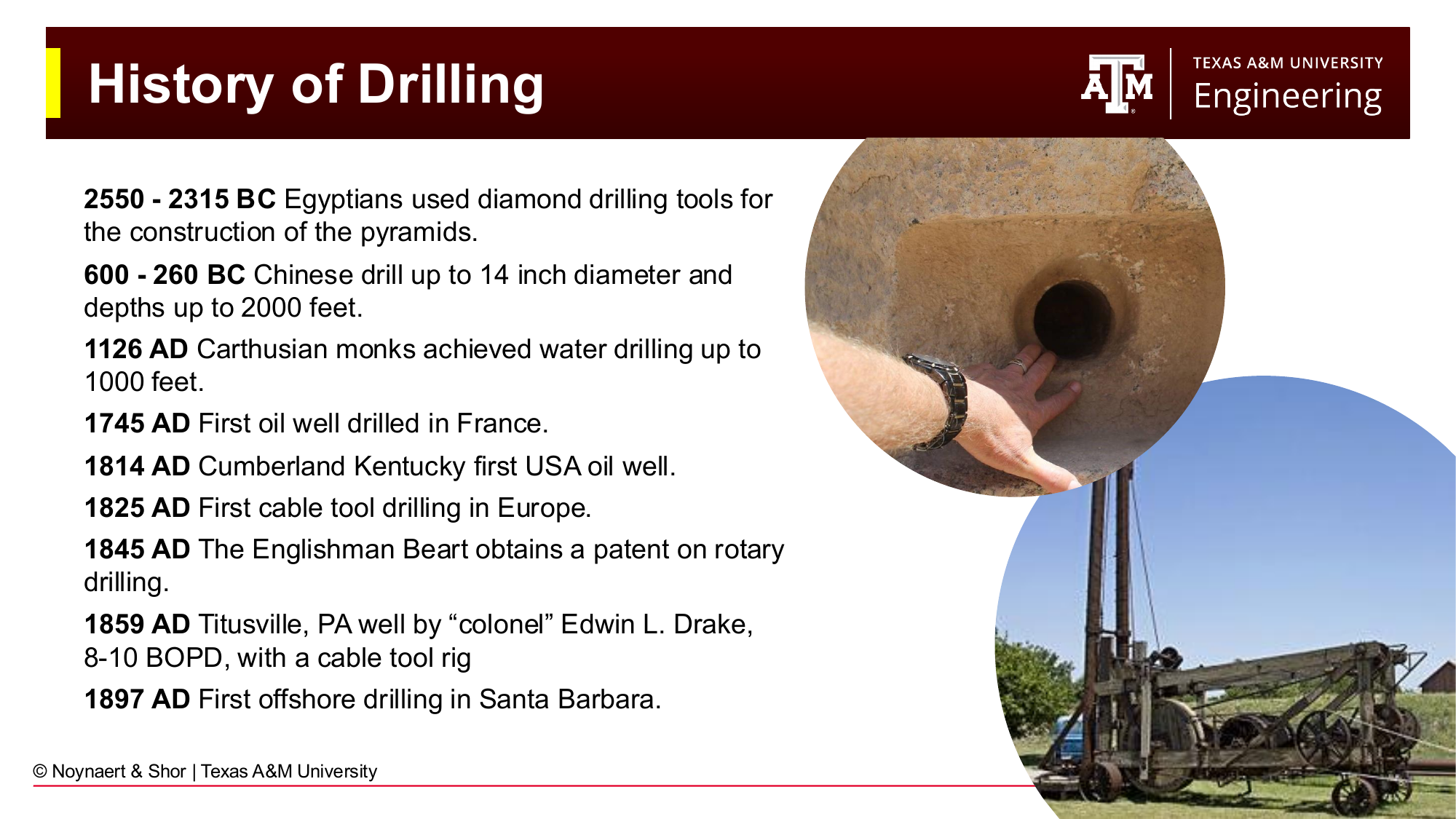
Fig. 8 Key milestones in drilling history from ancient Egypt through the first offshore well in 1897.#
The earliest known drilling dates to around 2550–2315 BC, when the Egyptians used rotating tools with abrasive materials — likely sand or diamond dust — to bore precise circular holes in stone during the construction of the pyramids. During this time period, water wells and cisterns were typically hand excavated with shovels and chissels, but were shorn using clay, masonry, or stone. Roughly 2,500 years ago, Chinese engineers were drilling water wells up to 600 m (2,000 ft) deep using bamboo drill strings and percussion methods. In 1126 AD, Carthusian monks in France drilled wells over 300 m (1,000 ft) deep to access fresh water — these are among the earliest recorded artesian wells in Europe.
The modern petroleum era began in the mid-19th century:
1745 — The first recorded oil well of the modern period was drilled in Pechelbronn, France, to produce oil for lamp fuel and lubricants.
1814 — The first oil well in the United States was drilled in Cumberland, Kentucky.
1859 — Edwin Drake’s well at Titusville, Pennsylvania, drilled with a cable tool rig, is often cited as the birth of the US commercial petroleum industry. It produced 8–10 barrels of oil per day (BOPD) and sparked a regional oil rush.
1897 — The first offshore well was drilled from a pier extending into the Pacific Ocean off Santa Barbara, California, targeting oil seeps that Spanish explorers had documented in the 1600s. George Vancouver, a midshipman under Captain James Cook, wrote in 1792:
The surface of the sea, which was perfectly smooth and tranquil, was covered with a thick, slimy substance, which when separated or disturbed by a little agitation, became very luminous, whilst the light breeze, which came principally from the shore, brought with it a strong smell of tar, or some such resinous substance.
The 20th century brought rapid technological advancement:
1900 — The Spindletop well in Beaumont, Texas (drilled by Patillo Higgins and Anthony Lucas) blew out at 100,000 BOPD, the most prolific oil well seen to that date, and launched the Texas oil boom and the era of large-scale rotary drilling.
1908 — Rotary drilling is introduced, dramatically improving penetration rates in hard rock.
1929 — Bentonite clay was first added to drilling fluid after drillers noticed that a naturally clay-rich formation had stabilized a problematic wellbore. This accidental discovery led to the modern science of drilling fluids.
1933 — Howard Hughes Sr. developed the first tri-cone roller bit, a design still in widespread use today.
1955 — The first purpose-built drill ship was deployed, opening the deep-water frontier.
2007 — The Kola Superdeep Borehole in Russia reached a depth of 40,230 ft (12.26 km), the deepest hole ever drilled. It was a scientific project, not an oil well.
2011 — Exxon Neftegas set a world record for extended-reach drilling (ERD) with the Odoptu OP-11 well off Sakhalin Island, Russia, reaching a total measured depth of 40,502 ft (7.67 miles). The well was drilled from an onshore rig on the beach, steering horizontally beneath the sea to reach an offshore reservoir, avoiding the need for an ice-class drill ship and the need for iceberg management.
A recurring theme in this history is that major advances often follow disasters. The Spindletop blowout in 1900 drove development of well control equipment. The Deepwater Horizon blowout in 2010 fundamentally changed offshore regulation and blowout preventer design. Every major incident in the industry has, over time, made drilling safer.
2.2 Types of Wells Across the E&P Lifecycle#
Not all wells serve the same purpose. The type of well drilled, its design priorities, and its cost are all shaped by where a project sits in the E&P lifecycle introduced in Chapter 1.
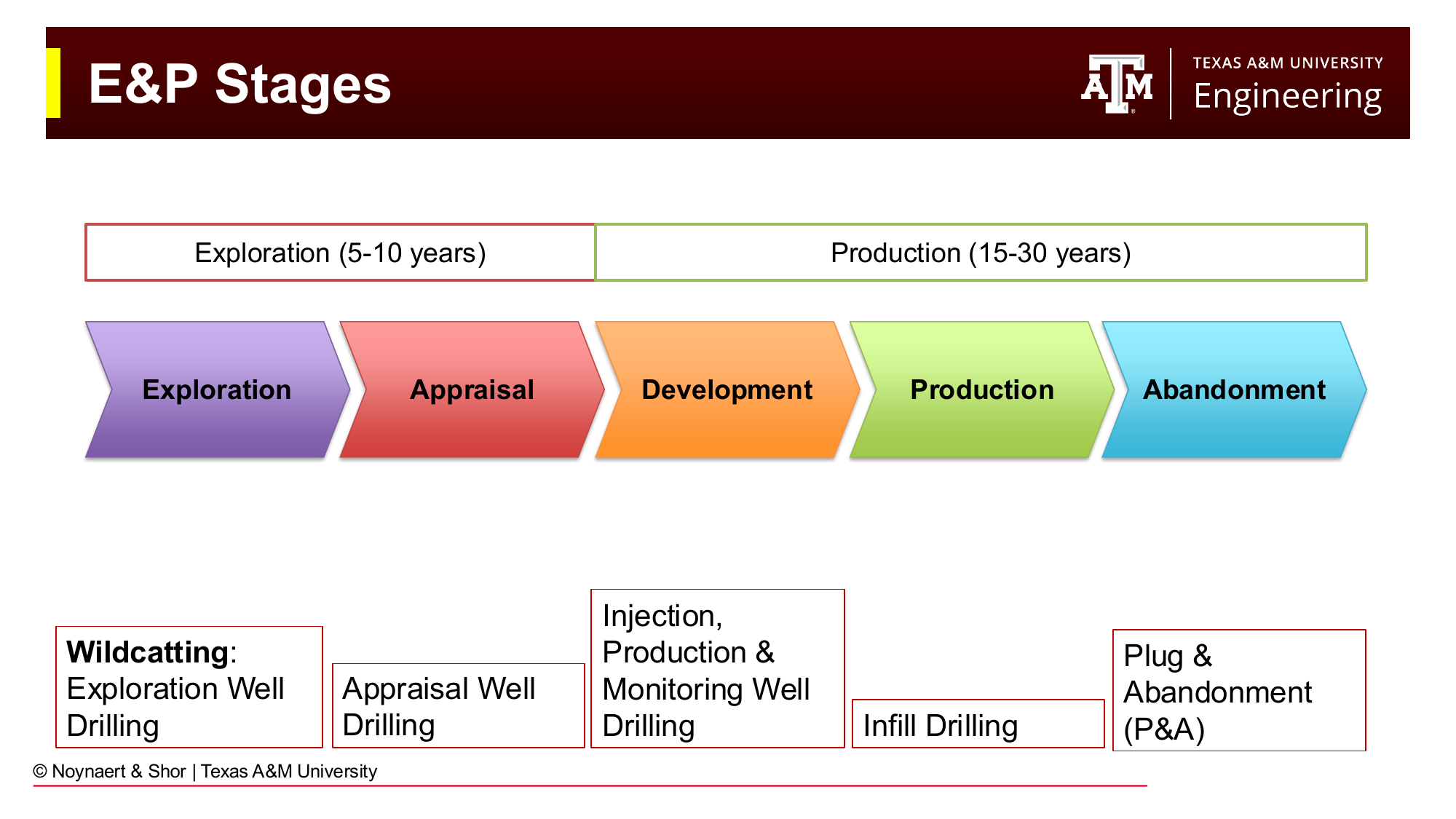
Fig. 9 The E&P lifecycle and the types of wells associated with each stage. The emphasis shifts from risk management and data gathering in early stages to cost optimization and production maximization in development.#
2.2.1 Wildcat (Exploration) Wells#
Wildcat wells are drilled when geologists believe hydrocarbons may exist in a region, but no wells have been drilled nearby to confirm it. The term “wildcat” reflects the high-risk, speculative nature of these wells — statistically, most exploration wells do not find commercial quantities of hydrocarbons.
Key characteristics of wildcat wells:
Over-designed for safety. Because the subsurface is largely unknown, the drilling program is conservative. Pore pressures and fracture gradients are estimated from regional data, not direct measurements, and the casing program typically includes extra safety margins.
Focused on data gathering. Cores, cuttings, well logs, and pressure tests are taken to characterize the formations penetrated.
Not optimized for speed. Performance drilling takes a back seat to safe, controlled drilling of unknown formations.
Reservoir preservation is critical. Excessive mud invasion into the reservoir rock can permanently damage permeability and make it impossible to evaluate or produce the well. The Davy Jones well in the Gulf of Mexico — targeting a massive natural gas reservoir at nearly 38,000 ft — is a cautionary example: the well was drilled successfully but the reservoir was so damaged by mud invasion that meaningful flow testing was never achieved, rendering a multibillion-dollar well essentially useless for evaluation purposes.
Key Term: Wildcat Well
A wildcat well (also called an exploration well) is a well drilled in an area with no nearby exploration or production history. Wildcat wells are inherently high-risk but are the mechanism by which new oil and gas fields are discovered. Less than 1 in 5 wildcat wells drilled globally results in a commercial discovery.
2.2.2 Appraisal Wells#
Once a discovery is confirmed, appraisal wells are drilled to define the size, quality, and producibility of the reservoir. The key questions appraisal drilling answers are: How large is this accumulation? Is the reservoir consistent across its extent? Can it be produced economically?
Appraisal wells are designed to minimize cost while maximizing data:
Slim hole design — smaller diameter than exploration or production wells, reducing cost while still providing the needed data
Usually vertical — vertical wells provide the simplest reservoir cross-section for evaluating formation properties
Often not completed for production — appraisal wells are typically plugged and abandoned, or converted to monitoring wells, after their data collection purpose is fulfilled
2.2.3 Development Wells#
Once a reservoir is proven commercial, development drilling begins. Development wells, which include both production wells and injection wells, are designed primarily for economic performance:
Production wells deliver hydrocarbons from the reservoir to the surface
Injection wells maintain reservoir pressure by injecting water or gas, or are used to dispose of produced water
Monitoring wells are instrumented with permanent sensors to track reservoir pressure, saturation, and deformation over time
Development wells benefit from everything learned in the exploration and appraisal phases. The reservoir properties, pressure regime, and formation characteristics are now well understood, enabling more aggressive and cost-effective well designs.
2.2.4 Infill Drilling#
As a field matures and reservoir pressure declines, infill wells may be drilled between existing wells to recover additional hydrocarbons from areas not adequately drained by the original well pattern. Infill drilling introduces a unique challenge: the new well must be drilled through formations that may have been depleted (their pressure reduced) by nearby production. Depleted zones have lower pore pressure than their original state, narrowing the margin between pore pressure and fracture gradient and potentially causing wellbore instability.
2.2.5 Plug and Abandonment (P&A)#
When a well has reached the end of its productive life, it must be permanently plugged and abandoned. P&A involves:
Placing cement plugs at specified intervals throughout the wellbore to prevent migration of formation fluids
Cutting the casing below the surface
Installing a surface cap and removing all surface equipment
Restoring the site to its original condition
A temporary P&A (or “temporary abandonment”) involves setting a retrievable plug to suspend the well without permanently sealing it and is used when the well may be re-entered for future operations.
P&A wells carry long-term liability implications. A well plugged to the standards of 1990 may fail decades later if subsurface conditions change — for example, if nearby injection operations pressurize formations that were at low pressure when the original plug was designed. This is why modern regulations for CO₂ sequestration projects require operators to locate and assess every abandoned well within the area of influence before commencing injection.
Key Term: Plug and Abandonment (P&A)
Plug and abandonment (P&A) is the process of permanently sealing a wellbore at the end of its operational life. Regulations specify minimum plug lengths and placement depths to prevent the upward migration of formation fluids. The operator typically bears long-term liability for the integrity of a P&A well.
2.3 The Drilling Process: Step by Step#
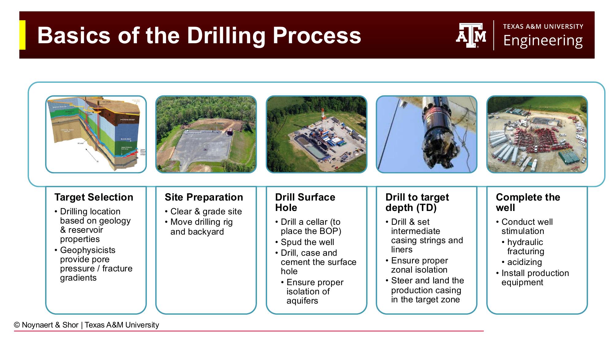
Fig. 10 The five major steps in the drilling process, from initial target selection through well completion.#
Step 1: Target Selection and Well Planning#
The drilling engineer begins work long before a drill bit touches rock. Geologists, geophysicists, and reservoir engineers define the target — the depth, location, and orientation of the zone to be penetrated — and provide the drilling engineer with the subsurface data needed to design the well.
Key inputs to well planning include:
Structural maps and stratigraphic cross-sections — define the geometry of the target reservoir and the rock sequence above it
Pore pressure profile — the fluid pressure in the formation at each depth (must be exceeded by the drilling fluid pressure to prevent fluid influx)
Fracture gradient profile — the pressure at which the formation rock will fracture (must not be exceeded or the wellbore will lose fluid to the formation)
Rock mechanics data — strength, elastic properties, and in-situ stresses of the formations to be drilled
Lease boundaries and surface constraints — legal and physical limits on where the well can be located
The drilling engineer uses these inputs to design every aspect of the well: casing setting depths and dimensions, cement program, drill string components, drill bit selection, drilling fluid properties, directional profile, and well control procedures.
This entire design effort is formalized in a document called a DWOP — Drill Well on Paper. The DWOP is reviewed in a meeting between the operator, drilling contractor, and all major service companies before any field work begins. Its purpose is to ensure everyone involved understands the plan and has identified potential risks and mitigation strategies before they become problems at the wellsite.
Key Term: DWOP (Drill Well on Paper)
A DWOP is a comprehensive pre-well planning exercise in which the drilling engineer designs every aspect of the well before the rig is mobilized. The DWOP is analogous to architectural drawings for a building: it is the complete specification that the drilling team will execute. Reviewing the DWOP with all contractors before spudding catches design conflicts and knowledge gaps while changes are still inexpensive.
Step 2: Site Preparation#
Once the well location is approved, the wellsite must be prepared before the rig arrives. Site preparation ranges from a few hours (a simple bulldozing of a flat area in a remote desert) to nine months or more (a fully engineered concrete pad with fluid containment, water treatment, and utility infrastructure in an environmentally sensitive location).
Regardless of scale, site preparation typically includes:
Clearing and grading the land surface to create a level pad
Installing the cellar — a shallow pit excavated at the wellhead location to accommodate the blowout preventer (BOP) stack and provide space for well control equipment
Road construction or upgrade to handle heavy equipment traffic
Installation of temporary facilities — offices, accommodations, storage yards, and fuel tanks
Being a good neighbor. Drilling is a 24-hour, 7-day-a-week operation. When well pads are located near residential areas, the drilling team must actively manage their impact:
Noise — sound walls can reduce noise levels in adjacent neighborhoods, though early experience in Colorado showed that walls without windows led to public complaints about what was being “hidden” rather than appreciation for the noise reduction. Transparency, both literal (windows in sound walls) and figurative (community communication, matters
Light pollution — rig lighting must illuminate the work area but should be directed downward and inward to minimize spillover into surrounding neighborhoods
Traffic — heavy equipment loads should be scheduled during off-peak hours, avoiding school drop-off times and overnight hours where possible; operators frequently upgrade local roads as part of their community commitments
Step 3: Drilling the Surface Hole and Setting Surface Casing#
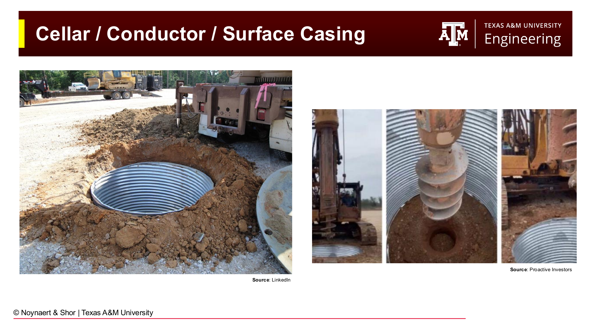
Fig. 11 Installation of the cellar, conductor casing, and surface casing — the first structural elements of the well. The BOP stack is installed on the surface casing before drilling continues into pressurized formations.#
Before the main rig arrives, a smaller rig typically drills and installs the conductor casing (18–36 inch hole), the first and shallowest casing string. The conductor provides structural support for the wellhead and seals off very shallow, unconsolidated soils.
Once the main rig is rigged up, the first major drilling operation is spudding the well, the industry term for officially starting to drill, and drilling the surface hole section. This section is drilled through the shallow formations that include any freshwater aquifers in the area. At the end of this section, surface casing (typically 10–18 inch diameter) is run and cemented in place.
Protection of freshwater aquifers is one of the most critical functions of surface casing. Once surface casing is cemented, the BOP stack is installed on top of it. The BOP is the primary mechanical barrier against well blowouts and must be in place before drilling into deeper, higher-pressure formations.
Step 4: Drilling to Total Depth#
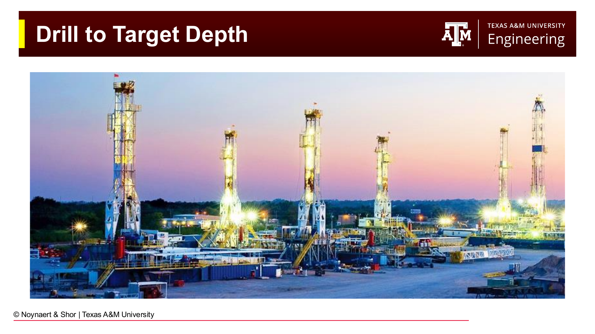
Fig. 12 Progressive drilling and casing to total depth. Each casing string is cemented before drilling continues with a smaller-diameter bit.#
After surface casing is set, the well is deepened in sections, with each section ending in another casing string cemented in place. The casing program steps down in diameter as the well gets deeper, creating the characteristic telescoping geometry described in Chapter 1.
The drilling engineer monitors the well continuously during this phase, adjusting mud weight to maintain pressure control, watching for signs of wellbore instability, and steering the wellbore if a directional profile is required. Real-time data from sensors in the drill string (called MWD/LWD — Measurement While Drilling / Logging While Drilling) provide information on the formations being drilled, the trajectory of the wellbore, and the condition of the drill string.
When the drill bit reaches the target depth, called Total Depth (TD), drilling stops and the final suite of wireline logs is typically run to characterize the reservoir before the production casing or liner is installed.
Step 5: Well Completion#
Once the production casing or liner is in place and cemented, the rig’s drilling work is done. The rig is typically released at this point (in a single-well operation) or moved to the next location on a multi-well pad. The well completion phase that follows, conducted by a completion crew rather than a drilling rig, includes:
Perforating the production casing to create channels between the wellbore and the reservoir
Well stimulation — hydraulic fracturing (pumping fluid at high pressure to create fractures in the rock) or acidizing (pumping acid to dissolve near-wellbore damage), depending on the reservoir type
Installing production equipment — tubing, packers, artificial lift systems (pumps or gas lift), and surface processing equipment
2.4 Well Planning in Detail#
2.4.1 Pore Pressure and Fracture Gradient#
Two of the most important inputs to well planning are the pore pressure gradient and the fracture gradient as functions of depth. Together, they define the “drilling window” — the range of mud weights that will keep the well stable.
Key Term: Pore Pressure Gradient
The pore pressure gradient is formation fluid pressure increases, presented as a function of depth, expressed in units of psi/ft or equivalent mud weight (ppg). A normal pore pressure gradient corresponds to a column of fresh water, approximately 0.433 psi/ft (equivalent to about 8.2 ppg mud weight). Overpressured formations have pore pressure gradients higher than normal.
Key Term: Fracture Gradient
The fracture gradient is the pressure at which the formation will fracture, expressed as a gradient in psi/ft or equivalent mud weight. The mud weight in the well must be kept below the fracture gradient to avoid losing drilling fluid into the formation (lost circulation).
The drilling fluid (mud) must be designed such that its hydrostatic pressure is:
Greater than the pore pressure at all depths (to prevent formation fluids from entering the wellbore)
Less than the fracture gradient at all depths (to prevent fracturing the formation and losing fluid)
Casing strings are set at depths where this window becomes too narrow — either because pore pressure is increasing rapidly, fracture gradient is decreasing, or a particularly troublesome formation must be isolated.
2.4.2 Responsibilities and Liability#
The drilling process involves multiple parties — the operator, the drilling contractor, service companies, and regulators — each with distinct roles and responsibilities.
The operator makes all final decisions about the well design, selects the contractors, and bears the primary financial and legal liability for the well throughout its lifetime — including after it is plugged and abandoned. The operator captures the upside (production revenue) and accepts the downside risk.
The drilling contractor provides the rig and crew, and executes the drilling plan according to the operator’s specifications. Drilling contractors are generally not responsible for the well design; they are responsible for safe and competent execution of the program they are given. Unless there is gross negligence, liability for well failures rests primarily with the operator.
Regulators (e.g., the Texas Railroad Commission at the Texas state level, or the Bureau of Safety and Environmental Enforcement (BSEE) offshore) establish the minimum standards for well construction and P&A. When a regulator approves a P&A design, that approval represents the standard of the time; it does not indemnify the operator against future failures if subsurface conditions change. This creates a complex liability landscape: a well properly plugged in 1990 may fail in 2025 due to pressure changes caused by nearby injection operations that could not have been anticipated at the time of abandonment.
This long-tail liability is one of the key reasons why thorough, conservative well design and documentation matter. The decisions made today may have consequences decades in the future.
Worked Examples#
Example 2.1 — Rig Day Rate and Well Cost Estimate#
Problem: A land rig with a day rate of $45,000/day is contracted to drill a well estimated to take 28 days to reach total depth, followed by 5 days for logging and casing. Additionally, the operator estimates $850,000 in fixed mobilization/demobilization costs and $1.2 million in service company costs (bits, mud, logging, cementing). Estimate the total well cost.
Solution:
Rig costs:
Total well cost:
Discussion: This estimate is a simplified AFE (Authorization for Expenditure), the formal cost document that an operator prepares before spudding. Real AFEs include contingency budgets (typically 10–20% of the base estimate) to cover unexpected events such as stuck pipe, formation problems, or weather delays. On a deeper or more complex well, the rig cost often dominates total well cost, which is why reducing non-productive time (NPT) is a central focus of drilling performance engineering.
Example 2.2 — Drilling Window Analysis#
Problem: A drilling engineer is planning a well in a formation with the following pressure data at 10,000 ft true vertical depth (TVD):
Pore pressure: 5,200 psi
Fracture gradient: 7,800 psi
Current mud weight: 10.0 lb/gal
(a) Is the current mud weight providing overbalance (i.e., is wellbore pressure greater than pore pressure)?
(b) Is the current mud weight below the fracture gradient?
(c) What is the “drilling window” in equivalent mud weight (EMW)?
Solution:
Hydrostatic pressure of current mud at 10,000 ft:
(a) Overbalance check:
The mud pressure exactly equals the pore pressure — this is balanced, not overbalanced. In practice, drillers maintain a positive overbalance margin (typically 100–300 psi). This mud weight is at the minimum safe limit.
(b) Fracture gradient check:
The mud pressure is well below the fracture gradient — no risk of lost circulation at this mud weight.
(c) Drilling window in EMW:
Convert pore pressure to equivalent mud weight:
Convert fracture gradient to EMW:
Interpretation: A 5.0 lb/gal drilling window is relatively comfortable. The drilling engineer has significant flexibility in mud weight design. In contrast, deepwater wells and overpressured formations often present windows as narrow as 0.5–1.0 lb/gal, requiring very precise mud weight management.
Example 2.3 — Selecting the Appropriate Well Type#
Problem: A company has acquired a seismic dataset over a previously undrilled basin in West Texas. The geophysical interpretation suggests a promising anticlinal structure at 9,500 ft depth that may contain oil. No wells have been drilled within 15 miles. Describe what type of well should be drilled first and what it should be designed to achieve.
Solution:
With no nearby analog wells, this is an exploration (wildcat) scenario. The first well should be an exploration well with the following design priorities:
Conservative mud weight program — pore pressure and fracture gradient must be estimated from regional analogues (offset wells in nearby basins). The mud program should be designed with a larger safety margin than in a well-understood area.
Comprehensive data collection program — the well should include: surface and formation samples (cuttings and core), a complete suite of wireline well logs (gamma ray, resistivity, density, neutron, sonic), formation pressure tests (MDT or RFT), and a production test if hydrocarbons are encountered.
Reservoir preservation — the mud program should include filtration control additives to minimize invasion of the target formation. The goal is to leave the reservoir as undamaged as possible so that pressure tests and flow tests are representative of the true reservoir.
Over-engineered casing program — with uncertain formation pressures, extra casing strings provide contingency if unexpectedly high pressures or unstable formations are encountered.
Safety focus over speed — rig time should not be sacrificed for performance. A slower, safer well that yields high-quality data is far more valuable than a fast well with a damaged reservoir or poor data.
If the well finds commercial hydrocarbons, the data collected will form the basis for designing the more cost-optimized appraisal and development wells that follow.
Practice Problems#
2.1 A rig has a day rate of $62,000/day. The planned well duration is:
Surface hole and casing: 4 days
Intermediate hole and casing: 8 days
Production hole and logging: 10 days
Total depth to rig release: 22 days
Mobilization and demobilization costs are $600,000. Service company costs (mud, bits, logging, cementing, directional) total $980,000. A contingency of 15% is applied to the total cost.
(a) Calculate the base well cost (excluding contingency). (b) Calculate the total well cost including contingency. (c) If the well encounters stuck pipe and loses 5 extra rig days, by how much does the total well cost increase?
Solution
(a) Base rig cost:
Base well cost: $\(\$1{,}364{,}000 + \$600{,}000 + \$980{,}000 = \mathbf{\$2{,}944{,}000}\)$
(b) Total cost with 15% contingency:
(c) Cost of 5 extra rig days:
Note: the contingency budget is intended to absorb exactly these types of unexpected events. Whether the stuck pipe cost is charged against contingency or as an overrun depends on how large the total NPT is relative to the contingency amount.
2.2 A well is being planned through a formation with the following pressure data:
Depth (ft TVD) |
Pore Pressure (psi) |
Fracture Pressure (psi) |
|---|---|---|
4,000 |
1,820 |
2,860 |
8,000 |
3,900 |
5,520 |
12,000 |
7,080 |
8,520 |
(a) Convert each pore pressure and fracture pressure to equivalent mud weight (EMW) in lb/gal. (b) Calculate the drilling window (in lb/gal) at each depth. (c) At which depth is the drilling window most constrained? What does this suggest about where a casing string might need to be set?
Solution
Use \(\text{EMW} = P / (0.052 \times D)\):
4,000 ft:
Pore: \(1820 / (0.052 \times 4000) = 8.75\) lb/gal
Frac: \(2860 / (0.052 \times 4000) = 13.75\) lb/gal
Window: 5.0 lb/gal
8,000 ft:
Pore: \(3900 / (0.052 \times 8000) = 9.38\) lb/gal
Frac: \(5520 / (0.052 \times 8000) = 13.27\) lb/gal
Window: 3.89 lb/gal
12,000 ft:
Pore: \(7080 / (0.052 \times 12000) = 11.35\) lb/gal
Frac: \(8520 / (0.052 \times 12000) = 13.65\) lb/gal
Window: 2.30 lb/gal
(c) The drilling window narrows with depth — from 5.0 lb/gal at 4,000 ft to only 2.3 lb/gal at 12,000 ft, indicating a zone of abnormally high pore pressure (overpressure) at depth. The rapid narrowing between 8,000 ft and 12,000 ft suggests that a casing string should be set at or before 8,000 ft to isolate the lower-pressure shallow formations before drilling into the higher-pressure deeper section with a heavier mud weight.
2.3 Classify each of the following well scenarios as wildcat, appraisal, development (production), development (injection), infill, or P&A, and briefly justify your answer.
(a) A company drills a vertical well 1 mile from a new discovery well to determine whether the reservoir extends that far.
(b) A company drills a horizontal well into a proven reservoir to produce oil. Offset wells have been producing from the same reservoir for 5 years.
(c) A company returns to a well that has been on production for 20 years and is now uneconomic, places three cement plugs, cuts the casing at 3 ft below ground, and caps the site.
(d) A company drills a well in a basin with no nearby production history, targeting an unproven structure identified on 3D seismic data.
(e) A company drills a well between two existing producers to access oil remaining in a portion of the reservoir not adequately drained by the original pattern.
Solution
(a) Appraisal well — testing the lateral extent of a known discovery
(b) Development (production) well — producing from a proven, developed reservoir
(c) Plug and abandonment (P&A) — permanently sealing an end-of-life well
(d) Wildcat (exploration) well — targeting an unproven structure with no nearby well control
(e) Infill well — placed between existing producers to recover bypassed reserves
2.4 A drilling engineer reviewing a P&A well file from 1988 discovers that the well was plugged with a single 100-foot cement plug set across the producing formation. Current regulations require a 300-foot plug across the formation plus a 100-foot surface plug. A nearby CO₂ injection project will begin operations 2 miles away next year.
(a) Under current regulations, is this well adequately plugged?
(b) What risk does the nearby CO₂ injection project create for this well?
(c) What would you recommend the operator do before the injection project begins?
Solution
(a) No. The existing 100-foot plug does not meet current regulations requiring a 300-foot formation plug plus a 100-foot surface plug. The well would need to be re-entered and re-plugged to meet current standards.
(b) The CO₂ injection project will increase subsurface pressure in the formations around the injection well. If the pressure increase propagates to the location of this well (2 miles away), the underpressured or inadequately sealed plug could be breached, allowing CO₂ or formation fluids to migrate upward through the wellbore and potentially reach the surface or contaminate shallow aquifers.
(c) Recommendations:
Re-enter the well and re-plug it to current regulatory standards (300 ft formation plug + 100 ft surface plug) before injection operations begin
Conduct a pressure integrity test on the re-plugged well
Install a monitoring instrument at the well to detect any pressure changes during injection operations
Notify the relevant regulator (e.g., Texas Railroad Commission) of the well’s location and P&A status and coordinate with the CO₂ injection project operator
2.5 A drilling company is planning to drill a well on a lease that borders a residential neighborhood in Colorado. The nearest homes are 500 feet from the planned rig location. List at least five specific measures the company should take to be a responsible neighbor during drilling operations, and briefly explain the purpose of each.
Solution
Answers will vary; the following are representative:
Install sound walls with transparent windows — reduces noise levels in adjacent properties; windows allow community members to see rig operations and reduce concerns about what is being hidden
Direct rig lighting inward and downward — prevents light pollution in neighboring homes during 24-hour operations
Schedule heavy equipment deliveries during daytime business hours — avoids traffic disruption during school drop-off, peak commute times, and overnight hours
Hold a pre-drilling community meeting — informs neighbors of the project timeline, what to expect, who to contact with concerns, and what measures are being taken; builds trust
Upgrade or repair the access road — heavy rig transport trucks damage road surfaces; proactively repairing these roads demonstrates good corporate citizenship
Implement a dust control program — water or chemical dust suppression on the access road and pad reduces particulate matter affecting neighboring properties
Establish a community liaison and complaint hotline — provides neighbors a direct, responsive point of contact for issues that arise
Summary#
This chapter has traced the drilling process from its ancient origins to the modern well planning workflow. Key points:
Drilling technology evolved over millennia from simple water wells to today’s precision-engineered extended-reach wells spanning over 40,000 ft. Major technological leaps — rotary drilling, roller cone bits, bentonite mud, drill ships — each unlocked new frontiers.
The type of well drilled depends on where a project sits in the E&P lifecycle. Wildcat wells prioritize safety and data over performance; development wells prioritize cost efficiency; P&A wells carry long-term liability implications that can extend decades beyond the end of production.
The drilling process follows five steps: target selection and well planning, site preparation, surface hole and casing, drilling to total depth, and well completion. The DWOP — drilling a well on paper — is the central planning document that guides all subsequent operations.
Pore pressure and fracture gradient define the drilling window — the range of mud weights that will keep the well stable without inducing lost circulation.
The operator bears primary liability for a well throughout its entire life. Decisions made during drilling and P&A may have consequences decades in the future, particularly as subsurface conditions change due to nearby operations.
References#
Mitchell, R.F. and Miska, S.Z. (eds.), Fundamentals of Drilling Engineering, Society of Petroleum Engineers, 2011.
Al-Majed, A.A., Hossain, M.E., and Al-Majed, A., Fundamentals of Sustainable Drilling Engineering, John Wiley and Sons, 2015.