
Chapter 20 — Drillstring Design#
Learning Objectives#
By the end of this chapter, students should be able to:
Identify the principal components of a drillstring, drill pipe, drill collars, and heavy weight drill pipe, and their specifications.
Calculate the weight in air of any steel tubular from its OD and ID, and apply the buoyancy factor to find its weight in mud.
Explain the neutral point concept and why it must remain in the drill collar section of a vertical well.
Calculate the length of drill collars required to achieve a target weight on bit.
Calculate the tensile load and margin of overpull for a drillstring and check against the pipe’s rated capacity.
Describe tapered string design and explain when it is required.
Calculate bending stress from dogleg severity and check combined loads on drill pipe with the von Mises criterion.
20.1 The Drillstring Design Problem#
The drillstring is everything between the top drive (or kelly) and the bit. Its functions are to (1) transmit rotational torque from the surface to the bit, (2) transmit weight on bit (WOB) from the surface down the wellbore, and (3) serve as the conduit for drilling fluid circulated down to the bit and back up the annulus.
Drillstring design shares its toolkit with the casing design of Chapter 19, the buoyancy factor, tensile load accumulation, and design factors all carry over, but the design goals differ fundamentally. Casing is a static pressure vessel; the drillstring is a rotating machine element. Instead of containing wellbore pressure, the drillstring must deliver weight to the bit without buckling, survive the bending of every dogleg it rotates through, and retain enough reserve tensile capacity to pull itself free if it gets stuck.
20.1.1 Drill Pipe#
Drill pipe makes up the majority of the string by length. It is specified by:
Outside diameter (OD): The tube body OD, not the tool joint OD. Common sizes range from 3½ in (slim hole) to 6⅝ in (offshore); 5 in and 5½ in are most common in land operations.
Nominal weight (lb/ft): Includes the tool joint; heavier pipe has a thicker wall.
Grade: Specifies minimum yield strength. Common grades are E-75 (75,000 psi yield), X-95, G-105, and S-135 (135,000 psi yield). Avoid high-strength grades (S-135 and above) in H₂S environments due to susceptibility to sulfide stress cracking.
Connection: Tool joints are threaded connections between stands. API connections include Regular (Reg), Internal Flush (IF), and Full Hole (FH). Premium connections (NOV Grant Prideco XT, Atlas Bradford Delta) provide higher torsional strength and metal-to-metal seals for demanding applications.
Tool joints are the enlarged, threaded sections at each end of a drill pipe joint. The female half is the box and the male half is the pin. Hard banding, a layer of abrasion-resistant material applied to the outer surface of the tool joint, prevents wear against the casing during rotation. Tool joints can be recut (rethreaded) a limited number of times before the tong grip area is consumed.
Pipe is manufactured with upsets, thickened pipe-body ends, to provide a stronger transition to the tool joint. The most common upset type is IEU (internal-external upset), which slightly reduces the ID and slightly increases the OD at the upset zone.
Drill pipe is sold in Range 2 (~30 ft joints, standard for single and triple rigs) and Range 3 (~45 ft joints, standard for doubles and super singles).
20.1.2 Drill Collars#
Drill collars are thick-walled, heavy steel tubes run at the bottom of the string. Because of their thick wall (typically solid cross-section with a 2–3 in bore), they are far stiffer and heavier per foot than drill pipe. Their primary purpose in vertical wells is to supply weight on bit: by keeping the neutral point (the point of zero axial stress) inside the collar section, the drill pipe above is maintained in tension and is protected from buckling.
Common collar sizes are 6 in and 6¾ in OD. Non-magnetic (non-mag) drill collars are machined from Monel or other non-ferromagnetic alloys; they are placed immediately above the bit to house MWD and LWD sensors without distorting the magnetic field used for directional measurement.
20.1.3 Heavy Weight Drill Pipe (HWDP)#
Heavy weight drill pipe (HWDP) is a transitional string element with an OD and connection similar to standard drill pipe but a much thicker wall, roughly twice the weight per foot of the equivalent drill pipe size. A 5½ in HWDP joint weighs approximately 49–50 lb/ft versus ~21–26 lb/ft for standard 5½ in drill pipe.
HWDP is flexible like drill pipe (unlike collars), making it suitable for use in curved sections. It is used to:
Apply WOB through high inclination sections and horizontal laterals where rigid collars cannot be deployed.
Reduce the stress concentration at the transition between drill collars and drill pipe in the BHA.
20.1.4 Bottom-Hole Assembly (BHA) Tools#
The bottom-hole assembly (BHA) is the collection of specialized tools directly above the bit. Common BHA components include:
Stabilizers: Short subs with near-gauge blades (~1/16 in under bit OD) that contact the wellbore wall. They center the BHA, reduce lateral vibration, and provide directional control in straight-hole assemblies. Only a limited number may be deployed due to the high torque generated by each stabilizer.
Drilling jars: Double-acting impact tools that can deliver an upward or downward blow to free a stuck string. Jars are activated by pulling up or down on the string with a defined overpull; when the jar fires, the stored energy is released as an impact load.
Pony collars: Short (~10 ft) drill collar subs used to adjust the BHA weight without running a full 30–90 ft collar.
Subs: Short threaded adapters that connect components with different connection sizes or types (crossovers, bit subs, stabilizer subs).
MWD/LWD tools: Measurement-while-drilling (MWD) and logging-while-drilling (LWD) tools collect and transmit drilling operational data to surface. Common data recorded includes gamma ray (GR) and toolface measurements for directional drilling, and vibration data for drilling performance monitoring.
Mud motors: are used in many BHAs, either to improve drilling performance, or in conjunction with a bent assembly, allow for directional steering.
Drill collars: Make up a majority of the BHA and provide stiffness to the assembly and weight-on-bit.
20.1.5 Drillstring Inspection#
Because drill pipe rotates under tension, bending, and torsion for hundreds of hours per well, fatigue cracking is a constant concern. Industry practice is to inspect approximately one-third of the string each well, rotating which third is pulled for inspection. Inspection methods include:
Visual inspection: Surface cracks, corrosion pitting, worn hard banding.
Magnetic particle inspection (MPI): Iron filings applied to a magnetized joint; cracks interrupt the magnetic field and attract filings. UV light reveals crack patterns not visible to the naked eye.
Ultrasonic inspection (UT): Measures actual wall thickness; detects internal corrosion and cracks not accessible from the outside.
20.2 Drillstring Weight and Buoyancy#
20.2.1 Weight in Air#
The weight per foot of any steel tubular can be calculated from its OD and ID:
where OD and ID are in inches and \(w_\text{air}\) is in lb/ft. This formula comes from the density of steel (65.5 lb/gal) and the cross-sectional area of the tube wall. It applies to drill pipe, drill collars, and casing alike. Manufacturer tables provide nominal weights that include tool joints (for drill pipe) or are simply the tube-body weight (for collars).
20.2.2 Buoyancy Factor#
When a tubular is submerged in drilling fluid, the fluid exerts an upward buoyant force that reduces the effective weight. The buoyancy factor is:
where \(\rho_\text{mud}\) is the mud weight in lb/gal (ppg) and 65.5 lb/gal is the density of steel. The buoyed weight of any section of the string is:
Example: Buoyancy Factor
For a 10 ppg mud: \(k_B = 1 - 10/65.5 = 0.847\). A drill collar section with an air weight of 100 lb/ft weighs effectively 84.7 lb/ft in the mud. For 12 ppg mud: \(k_B = 1 - 12/65.5 = 0.817\).
The buoyancy factor is the single most important correction factor in drillstring weight calculations. All tensile load calculations at depth use buoyed weights, not air weights. Air weights are relevant when transporting or moving drill pipe at surface.
20.3 The Neutral Point and Drill Collar Sizing#
20.3.1 Weight on Bit vs. Hookload#
When the bit is on bottom taking weight, the drillstring is in tension above the neutral point (the depth of zero axial force) and in compression below it. The hookload supports the string weight above the neutral point; the buoyed weight below it is what pushes on the bit.
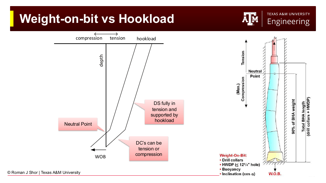
Fig. 245 Weight on bit vs. hookload. Above the neutral point, the string is in tension and supported by the hook; below it, the drill collars (and HWDP) are in compression, delivering their buoyed weight, reduced by inclination, to the bit. Good practice keeps the neutral point within the bottom-hole assembly, typically below 90% of BHA weight.#
Drill pipe is a long, thin column: in compression it buckles almost immediately, and a buckled, rotating pipe accumulates fatigue damage at its connections. The design rule follows: the neutral point must stay inside the drill collar (or HWDP) section, so that the drill pipe above never goes into compression. The stiff, thick-walled collars tolerate the compressive load.
20.3.2 Buckling#
The compressive load a tubular can carry before buckling depends on its stiffness, its weight, and the support provided by the wellbore. In vertical holes, even collars buckle beyond a critical compressive load, which is one reason a safety factor is applied to keep the neutral point well inside the collar section. In deviated holes, the low side of the wellbore supports the pipe, raising the critical buckling load substantially: the pipe first snakes sinusoidally along the low side, and only at higher loads spirals into helical buckling, which can lock the string against the wellbore wall.
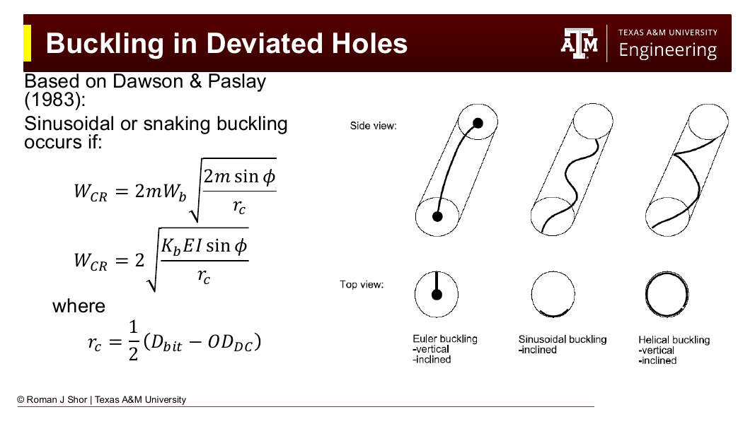
Fig. 246 Buckling modes of a tubular in a wellbore: Euler buckling (vertical and inclined), sinusoidal “snaking” buckling along the low side of an inclined hole, and helical buckling. The critical load for sinusoidal buckling in deviated holes (Dawson & Paslay, 1983) grows with wall support — one reason compression is tolerable in laterals but dangerous in vertical drill pipe.#
20.3.3 Required Collar Length#
The minimum collar length to deliver a target WOB with a safety factor SF is:
where:
\(WOB\) = desired weight on bit (lb)
\(SF\) = safety factor (typically 1.15–1.25; keeps neutral point inside collar section even with survey uncertainty)
\(w_c\) = collar weight per foot in air (lb/ft)
\(k_B\) = buoyancy factor (dimensionless)
\(\theta\) = inclination angle from vertical (degrees); for a vertical well, \(\cos(0°) = 1\)
The factor \(\cos\theta\) accounts for the component of collar weight acting along the wellbore axis; in inclined wells, some weight is transferred to the low side of the wellbore rather than transmitted to the bit.
Example: Drill Collar Sizing
Given: WOB = 50,000 lb; 6¾ in drill collars weighing 100 lb/ft; mud weight = 10 ppg; vertical well; SF = 1.15.
Solution: $\(k_B = 1 - \frac{10}{65.5} = 0.847\)$
At 30 ft per joint, this requires \(679/30 \approx 22.6\) joints → 23 joints (round up to the next whole joint). In the field, you might run 24 joints to have a full stand available.
20.3.4 Inclined Wells#
In inclined wells, HWDP is used to deliver WOB through the curved section instead of drill collars. Rigid drill collars cannot navigate build sections without imposing excessive bending loads on their connections. In horizontal laterals, the weight component along the borehole axis approaches zero (\(\cos 90° = 0\)), so all WOB is delivered by surface hydraulics (pushing with the bit weight supported by surface tension control) or by the weight of HWDP in the curve section — and, because the wellbore wall supports the pipe (Section 20.3.2), drill pipe in a lateral can safely run in compression that would buckle it in vertical hole.
20.4 Tensile Load Analysis and Margin of Overpull#
20.4.1 Total String Weight in Mud#
The total tensile load at the surface (hookload) is the sum of the buoyed weights of each string section:
where \(w_i\) and \(L_i\) are the air weight per foot and length of section \(i\). For a multi-component string (bit + collars + HWDP + drill pipe), sum the buoyed weight of each section separately.
20.4.2 Margin of Overpull#
The margin of overpull (MOP) is the additional pull force available above the string’s buoyed weight before the string reaches its tensile strength limit. It answers the question: if the drill string gets stuck, how much extra tension can we apply at surface to free it without parting the string?
A MOP of 100,000 lb is a common field target. The critical check point is at the top joint of drill pipe, where the tensile load is greatest:
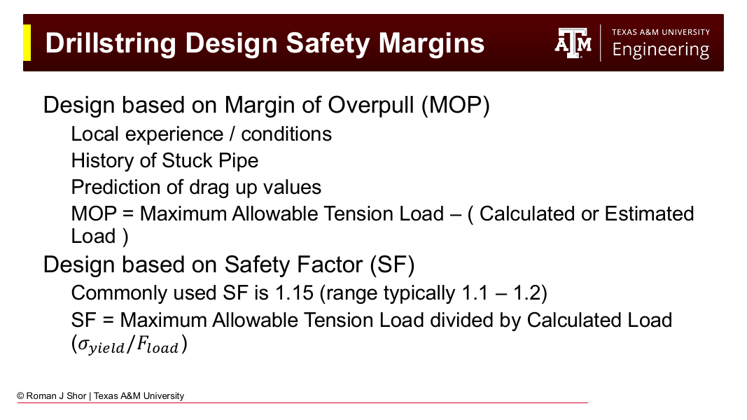
Fig. 247 The two drillstring tension design philosophies: margin of overpull (set from local experience, stuck-pipe history, and predicted drag) or a safety factor (commonly 1.15, typically 1.1–1.2) on the calculated load. Use one or the other — not both.#
MOP vs. Safety Factor
The margin of overpull is a more intuitive design tool than a safety factor for drillstring tension. A safety factor of 1.15 on a 200,000 lb string means you can pull 230,000 lb — but it doesn’t directly tell the driller how much extra pull is available. A MOP of 100,000 lb communicates that directly. Use either approach, but not both simultaneously: applying a DF and then also requiring a specific MOP is double-counting.
20.4.3 Critical Section Check#
The critical cross-section for tensile failure is always the top of the drill pipe (just below the traveling block / top drive), where the entire weight of the string below hangs. The check is:
If this check fails, the engineer must use a higher-grade or larger-wall-thickness drill pipe, or design a tapered string.
20.5 Tapered Drillstring Design#
On very deep wells, the cumulative weight of the drillstring can exceed the tensile capacity of the drill pipe. The solution is a tapered string: run a stronger (heavier wall or higher grade) pipe in the upper section and a lighter, cheaper pipe in the lower section.
The design procedure — a “bottoms-up” design, like the casing program of Chapter 18 — is:
Calculate the tensile load at each depth interval, working from the bit upward.
As long as the required tensile capacity stays within the rating of the lightest available pipe, run that pipe.
When the required capacity exceeds the lightest pipe’s rating, switch to the next heavier/stronger pipe at that depth.
Repeat until you reach surface.
The practical result is that the cheapest, lightest pipe fills the lower portion of the string (where loads are lower), and the heavier/stronger pipe is reserved for the upper section. In cost terms, less expensive pipe (lower grade, thinner wall) is the default — switch upward in strength only when forced to. The stress check at the top of each pipe section (where that section carries the most load) governs each transition depth.
20.6 Bending and Combined Loads on Drill Pipe#
In a deviated well, the drill pipe bends to follow every dogleg, and the bending stress adds to the axial tension on the outer wall of each bend. From the pipe’s bending moment and the wellbore curvature, the bending stress simplifies to a remarkably compact field formula:
with DLS in degrees per 100 ft, OD in inches, and \(\sigma_b\) in psi.
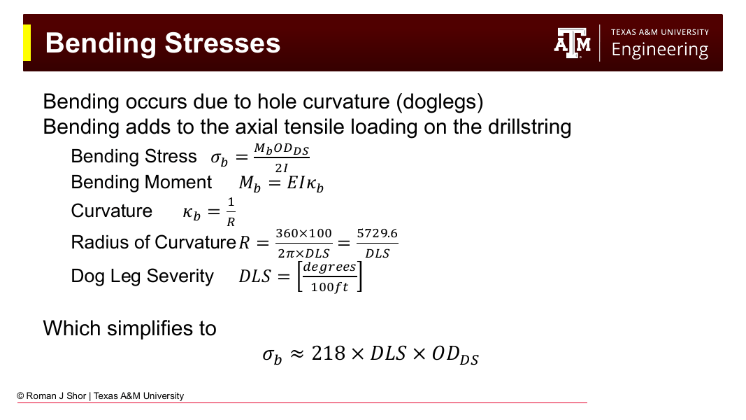
Fig. 248 Bending stress from hole curvature: the full derivation from bending moment \(M_b = EI\kappa_b\) and radius of curvature \(R = 5729.6/\text{DLS}\) collapses to the field formula \(\sigma_b \approx 218 \times \text{DLS} \times OD_{DS}\).#
The critical check location is the top of the build section, where the axial tension is greatest (the full string below hangs from it) and the bending begins. There, the combined state is evaluated with the simplified von Mises criterion introduced in Chapter 19:
where \(\sigma_A\) is the axial stress, \(\tau\) the torsional shear stress (often negligible for a first check), and a design factor of ~1.2 is typical for drill pipe. For rotating drill pipe the bending stress is also cyclic, each rotation moves a given point from the tension side to the compression side of the bend, which is why dogleg severity limits for rotating drill pipe are ultimately fatigue limits, and why the torque and drag and vibration considerations of Chapter 13 sit alongside this static check in practice.
Chapter Summary#
The drillstring is designed from the bit up. Drill collars (and HWDP in deviated wells) supply weight on bit, sized so that the neutral point, the transition from compression to tension, stays safely inside the BHA:
Weight calculations start from the steel formula \(w_\text{air} = 2.67(OD^2 - ID^2)\) and apply the buoyancy factor \(k_B = 1 - \rho_\text{mud}/65.5\) to every submerged component. The total buoyed string weight gives the hookload; the gap between the top drill pipe joint’s tensile rating and that hookload is the margin of overpull: the reserve pull available to free a stuck string. Where one pipe cannot carry the string to total depth, a tapered design runs stronger pipe up top and lighter pipe below, checked at the top of each section.
In deviated wells, bending stress \(\sigma_b \approx 218 \times \text{DLS} \times OD\) adds to axial tension at every dogleg, with the top of the build section as the critical location for the von Mises combined-load check. Compression that would buckle drill pipe in vertical hole is tolerable in laterals, where the wellbore wall supports the pipe — the physics that makes modern horizontal drilling possible.
Key Equations Summary#
Quantity |
Formula |
Units |
|---|---|---|
Weight in air |
\(w = 2.67 \times (OD^2 - ID^2)\) |
lb/ft (OD, ID in inches) |
Buoyancy factor |
\(k_B = 1 - \rho_\text{mud}/65.5\) |
dimensionless |
Buoyed weight |
\(w_b = k_B \times w_\text{air}\) |
lb/ft |
Drill collar length |
\(L_c = WOB \times SF / (w_c \times k_B \times \cos\theta)\) |
ft |
Surface load |
\(F_\text{surface} = k_B \sum w_i L_i\) |
lb |
MOP check |
Pipe yield \(\geq F_\text{surface} + \text{MOP}\) |
lb |
Bending stress |
\(\sigma_b = 218 \times \text{DLS} \times OD\) |
psi (DLS in °/100 ft) |
Von Mises |
\(\sigma_e = \sqrt{(\sigma_A + \sigma_b)^2 + 3\tau^2}\) |
psi |
Practice Problems#
20.1. A drillstring consists of the following sections in a vertical well drilled with 12 ppg mud:
6¾ in drill collars, 95 lb/ft in air, 600 ft
5½ in HWDP, 49 lb/ft in air, 300 ft
5 in drill pipe (S-135), 19.5 lb/ft in air, 9,100 ft
(a) Calculate the buoyancy factor.
(b) Calculate the buoyed weight of each section.
(c) Calculate the total hookload (surface tensile load) in mud.
(d) The S-135 pipe has a tensile yield strength of 551,000 lb. Calculate the margin of overpull available.
20.2. A vertical well requires WOB = 40,000 lb. The drill collars available are 6 in OD, 2 in ID, and run in 10 ppg mud.
(a) Calculate the air weight per foot of the 6 in drill collars using \(w = 2.67(OD^2 - ID^2)\).
(b) Calculate the buoyancy factor and buoyed weight per foot.
(c) Calculate the minimum collar length required with a safety factor of 1.15.
(d) How many 30-ft collar joints are needed? Round to the nearest whole joint.
20.3. The drillstring in a build-and-hold well consists of 5½ in drill pipe (S-135, yield 597,000 lb, OD = 5.5 in) through a build section with a dogleg severity of 5°/100 ft. The axial tensile stress at the top of the build section is 42,000 psi.
(a) Calculate the bending stress at the top of the build section using \(\sigma_b = 218 \times \text{DLS} \times OD\).
(b) Calculate the von Mises equivalent stress (assume torsion is negligible, \(\tau = 0\)), so \(\sigma_e = \sigma_A + \sigma_b\).
(c) Check whether the pipe is safe with a design factor of 1.2 (\(\sigma_e \times 1.2 \leq Y_p\)).
(d) If the drill pipe is not safe, what grade or size change would you recommend?
20.4. A deep vertical well has a 15,000 ft drillstring. The upper 5,000 ft will use 5½ in Grade S-135 drill pipe (tensile yield 597,000 lb, 25.6 lb/ft in air), and the lower 10,000 ft will use 5 in Grade S-135 drill pipe (tensile yield 501,000 lb, 19.5 lb/ft in air). Mud weight is 11 ppg.
(a) Calculate the buoyancy factor.
(b) Calculate the tensile load at the top of the lower drill pipe section (i.e., the load applied to the bottom of the upper section).
(c) Calculate the total hookload at surface.
(d) With a required margin of overpull of 100,000 lb, is the upper drill pipe adequate?
20.5. Explain in your own words:
(a) Why drill collars are run at the bottom of the string rather than drill pipe, for vertical wells.
(b) Why rigid drill collars are generally not deployed through build sections or into horizontal laterals.
(c) What the neutral point is, where it should be kept, and what happens if it moves into the drill pipe section.
(d) Why the margin of overpull is a more field-intuitive concept than a tensile safety factor.
(e) Why drill pipe can safely run in compression in a horizontal lateral but not in a vertical hole.