
Chapter 18 — Casing Design: Selecting Setting Depths#
Learning Objectives#
By the end of this chapter, students should be able to:
Describe the bottoms-up methodology for casing design and explain why it starts with the production interval rather than the surface.
Use a pore pressure / fracture gradient profile to identify the depths at which casing must be set.
Apply the drilling window concept to determine why a casing string is needed at a particular depth.
Use a bit/casing compatibility chart to determine appropriate hole sizes and casing ODs for each string in a program.
Explain the real-world design criteria that influence setting depth beyond the pore pressure gradient.
Identify problem zones (overpressured, depleted, unstable, salt) and describe how they affect casing design.
18.1 The Bottoms-Up Design Philosophy#
The fundamental rule of casing program design is: start at the bottom. This is the “bottoms-up” methodology, and it reflects a simple engineering reality: the casing OD at any given depth is constrained by the ID of the casing string above it, and the casing string above it is constrained by the one above that. If you start at the top, you have no way of knowing whether the eventual production string will fit inside the wellbore you’ve designed.
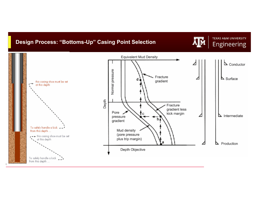
Fig. 223 The bottoms-up design process begins with completion requirements and works upward to the surface.#
The design process flows from bottom to top:
Start with the completion. What is the completed well going to do? What OD production tubing is required? What is perforation gun diameter? What wireline tools will need to pass through the production string? The completion drives the production string ID requirement.
Select the production string. Given the required minimum ID, choose the production casing OD, nominal weight, grade, and connection. The OD of the production string determines the minimum bit size needed to drill the production interval.
Determine the bit size for the production interval. The bit must be large enough to pass through the previous casing string (clearance constraint) and large enough to allow the production casing to be run and cemented. Typically 1–3 in of annular clearance is desired for cementing.
Select the previous casing string OD. Work backward: the bit size for the production interval determines the minimum drift ID of the previous intermediate string. The previous string’s drift ID must be larger than the bit. This determines the previous string’s OD and weight.
Continue upward until the outermost string (conductor) is defined.
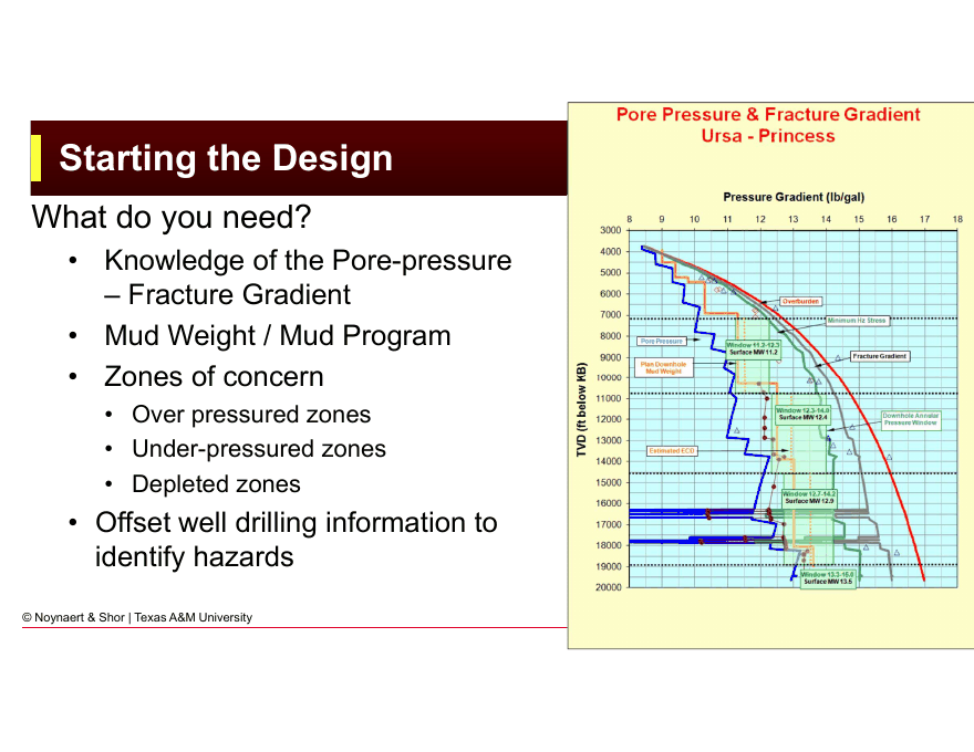
Fig. 224 Starting the casing design from the completion requirements. The production tubing OD sets the minimum production casing ID, which in turn drives all string sizes upward.#
This bottom-up constraint chain means that a change to the production string ripples through the entire casing program. If the completion engineer selects a larger tubing OD late in the planning process, the entire casing program may need to be redesigned.
18.2 The Drilling Window and Setting Depths#
The pore pressure and fracture gradient profile is the most important input to setting depth selection. The drilling window, the gap between pore pressure and fracture gradient expressed in equivalent mud weight (ppg), determines how far you can drill before you must set casing.
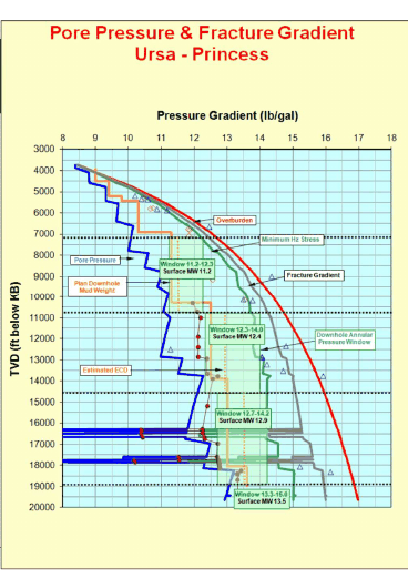
Fig. 225 A pore pressure / fracture gradient profile defines the drilling window at every depth. The gap between PP and FG determines how far a given mud weight can drill before either well control or lost circulation is encountered.#
18.2.1 Why the Window Forces a Casing Point#
During drilling, the mud weight must be kept between two limits at every depth:
If mud weight falls below pore pressure, formation fluids can influx (kick). If mud weight exceeds fracture gradient, the formation breaks down and drilling fluid is lost (lost circulation). The difference between these limits is the drilling window.
The drilling window is not constant: it changes with depth. Two scenarios force a casing point:
Scenario 1: The window narrows to zero. If pore pressure increases faster than fracture gradient with depth, the window eventually closes. You cannot increase mud weight to control a deeper zone without fracturing a shallower zone. A casing string must be set above the narrow window to isolate the weaker zone before drilling ahead with heavier mud.
Scenario 2: The mud weight required for the next zone exceeds the Maximum Allowable Annular Surface Pressure (MAASP). Even if there is still a theoretically open window at depth, the maximum allowable surface pressure (MAASP) at the current casing shoe limits the ability to circulate out a kick at depth. If the mud weight needed to drill deeper would require holding surface pressures above MAASP during a kick, a new casing string is required.
Key Term
The drilling window at any depth is the range of mud weights bounded below by pore pressure (kick limit) and above by fracture gradient (lost circulation limit). Expressed in ppg equivalent mud weight. A casing string must be set whenever the window narrows sufficiently to prevent safe drilling of the next interval.
18.2.2 Reading a PP-FG Profile for Casing Design#
The procedure for reading a pore pressure and fracture gradient profile to identify casing setting depths is:
Start at target depth (TD). Identify the pore pressure and fracture gradient at the planned TD. The mud weight required to drill into the objective must be at least equal to the pore pressure EMW at TD.
Project the mud weight upward. Holding the mud weight required at TD constant, trace it upward on the PP-FG profile. As you move upward, the fracture gradient typically decreases. At some depth, the constant mud weight line approaches (or crosses) the fracture gradient; this is where the previous casing shoe must be set. Above the shoe, the fracture gradient is the constraint; below the shoe, the shoe acts as the controlling weak point.
Continue upward. From the shoe depth just identified, determine the new mud weight required to drill from that shoe down to TD. Now trace this (lighter) mud weight upward. As you move toward surface, the fracture gradient again decreases at some shallower depth, identifying the next shallower casing shoe.
Continue until you reach surface. Each iteration identifies one casing shoe, working from the bottom to the surface.
This is the simplified version of the bottoms-up method applied to the PP-FG profile. In practice, a safety margin is added to the mud weight (trip margin, typically 0.5 ppg or more), and the actual shoe depth is adjusted for operational considerations.
18.3 Casing OD Selection#
Once the setting depths are established, the ODs of each string must be selected. The constraint is that each casing string must fit inside the one above it, with sufficient annular clearance for cementing.
18.3.1 Bit/Casing Compatibility Chart#
The bit/casing compatibility chart (or bit-casing chart) is a reference table that shows the standard combinations of bit size and casing OD that provide adequate clearance for running and cementing. The chart reflects decades of industry experience and tooling standards.
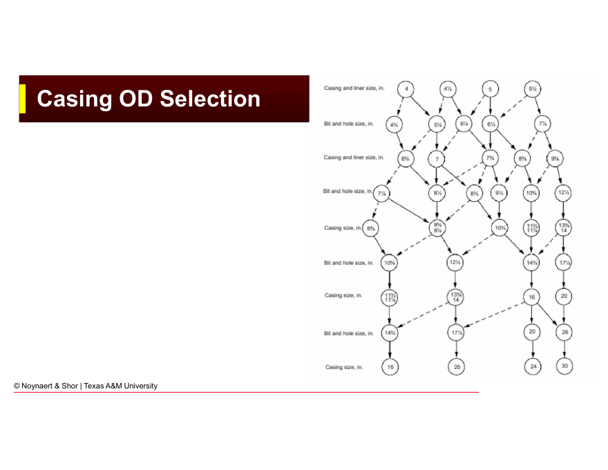
Fig. 226 Bit/casing compatibility chart. Each cell shows whether a given bit size / casing OD combination provides adequate clearance for running and cementing.#
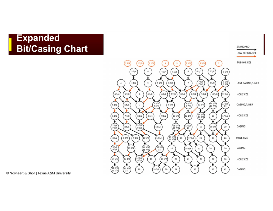
Fig. 227 Expanded bit/casing chart showing additional combinations. The chart is the starting point for selecting string sizes; final clearances should always be verified with actual casing weight and wall thickness.#
How to use the chart:
Start with the production casing OD (selected based on completion requirements).
Read the chart to identify the recommended bit size to drill the production interval.
The chosen bit size must fit inside the previous string (intermediate casing). Read the chart to find an intermediate casing OD compatible with that bit size.
Repeat upward through all strings.
Example
Reading the chart:
Production casing: 7 in
Bit to drill production interval: 8½ in (from chart)
Intermediate casing drift ID must exceed 8½ in
Compatible intermediate casing OD: 9⅝ in (drift ID ≈ 8.525 in ✓)
Bit to drill intermediate interval: 12¼ in (from chart)
Surface casing drift ID must exceed 12¼ in
Compatible surface casing OD: 13⅜ in (drift ID ≈ 12.515 in ✓)
18.3.2 Minimum Clearance Requirements#
The bit/casing chart builds in standard clearances, but the engineer should verify that the minimum annular space for cementing is adequate. Typical guidelines:
Minimum 0.5 in radial clearance (1 in diametrically) between casing OD and borehole wall for cementing
Preferred 0.75–1 in radial clearance for reliable cement placement
Tool joints on drill pipe must pass through the casing with sufficient clearance to avoid excessive drag
In tight wellbore programs (e.g., very deep wells with many strings), clearances become critically small and premium connections (with smaller coupling OD than standard T&C) become necessary to maintain adequate clearance.
18.4 A Worked Example: Three-String Casing Program#
The following example illustrates the bottoms-up design process for a moderately deep land well.
Given:
Planned TD: 12,500 ft TVD
Pore pressure at TD: 12.0 ppg EMW
Fracture gradient at shoe of intermediate casing: 14.5 ppg EMW
Freshwater table: 500 ft
Regulatory surface casing requirement: 1,000 ft minimum
Completion: requires 2⅞ in production tubing (minimum production casing ID ≈ 4.0 in)
Trip margin: 0.5 ppg
Step 1: Production string
The completion requires a minimum ID of 4.0 in. Checking the casing tables:
4½ in × 9.5 lb/ft × N80 × LTC: Nominal ID = 4.090 in, Drift = 3.965 in ← insufficient
4½ in × 9.5 lb/ft × N80 × LTC: Drift = 3.965 in
5 in × 15 lb/ft × N80 × LTC: Nominal ID = 4.408 in, Drift = 4.283 in ← marginal
5½ in × 15.5 lb/ft × N80 × LTC: Nominal ID = 4.950 in, Drift = 4.825 in ✓
Select: 5½ in × 15.5 lb/ft × N80 × LTC set at 12,500 ft
Step 2: Bit for production interval
From bit/casing chart for 5½ in casing: 8½ in bit
Step 3: Previous string (intermediate casing)
The 8½ in bit must fit inside the intermediate casing. From the chart, 9⅝ in casing has drift ID ≈ 8.525 in (fits 8½ in bit ✓).
Mud weight for production interval: 12.0 + 0.5 (trip margin) = 12.5 ppg
Setting depth of intermediate casing: Trace 12.5 ppg upward on the PP/FG profile. If fracture gradient at ~8,000 ft TVD is ≈ 13.0 ppg, the 12.5 ppg mud line intersects the FG line at roughly 8,000 ft. Set intermediate casing at 8,000 ft.
Select: 9⅝ in intermediate casing at 8,000 ft
Step 4: Bit for intermediate interval
From chart for 9⅝ in casing: 12¼ in bit
Step 5: Surface casing
The 12¼ in bit must pass through the surface casing. From chart, 13⅜ in casing has drift ID ≈ 12.515 in ✓
Regulatory requirement: minimum 1,000 ft. Freshwater protection requires setting below 500 ft. Setting depth: 1,200 ft (below all freshwater, satisfies regulation).
Select: 13⅜ in surface casing at 1,200 ft
Step 6: Bit and conductor
From chart for 13⅜ in casing: 17½ in or 17 in bit Conductor: 20 in driven to 50 ft
Final casing program:
String |
OD (in) |
Setting Depth (ft) |
Purpose |
|---|---|---|---|
Conductor |
20 |
50 |
Structural / wellhead support |
Surface |
13⅜ |
1,200 |
Freshwater protection / BOP anchor |
Intermediate |
9⅝ |
8,000 |
Isolates overpressured shale above |
Production |
5½ |
12,500 |
Production barrier |
18.5 Real-World Design Criteria#
The PP-FG profile and bottoms-up methodology give a starting point, but actual casing setting depth selection involves additional engineering judgment.
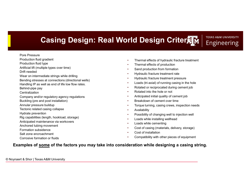
Fig. 228 Real-world casing design criteria extend beyond the pore pressure gradient to include formation stability, regulatory requirements, and operational risk.#
18.5.1 Formation Stability and Mechanical Issues#
Not all wellbore instability is pressure-related. Some formations are mechanically weak regardless of mud weight:
Reactive shales swell when exposed to water-based mud, regardless of hydrostatic pressure. Casing through reactive shale prevents time-dependent wellbore collapse and allows the shale to be bypassed with a different mud type below.
Unconsolidated formations near surface slough into the wellbore continuously. Casing provides structural support.
Salt formations creep plastically under overburden stress, closing the wellbore over time. Casing through salt must be set at a depth where the section is stable, and the casing itself must be designed to resist the lateral confining pressure from creep (external collapse loading).
The potential for breakout should be evaluated if stresses are well known. Breakout and wellbore fracturing may reduce the size of the drilling window.
18.5.2 Zonal Isolation Requirements#
Regulatory and operational isolation requirements are often more stringent than what the pressure gradient alone would indicate:
Freshwater isolation: In most jurisdictions, casing must be set through all freshwater-bearing formations and cemented completely to surface. The depth of the freshwater/saline interface is often defined by regulation, not by pore pressure.
Geothermal and environmental zones: Some regulatory environments require isolation of geothermal aquifers or specific intervals.
Production isolation: Some completion designs require that specific intervals be isolated from each other even if they have similar pressures.
18.5.3 Logistics and Cost#
The depth at which a formation sits relative to available casing ODs, rig limitations, and available cement volumes can shift the optimal setting depth. Setting casing at a convenient depth (just above a problem zone) may be slightly different from the theoretically optimal depth derived from the pressure profile.
Casing depth also affects the cost of the cement job. Intermediate strings set deeper require more cement, more mixing time, and sometimes special cement formulations. The engineer must balance the benefit of deeper isolation against the cost.
18.5.4 Contingency and Risk#
On exploration wells and frontier area wells, the pore pressure and fracture gradient profiles are uncertain. Contingency strings, extra casing strings included in the plan but set only if needed, are common. The operator decides before drilling how many contingency strings are available and at what depth triggers they will be used.
18.6 Problem Zones and Their Impact on Design#
Several geological situations significantly complicate casing design:
18.6.1 Overpressured Zones#
An overpressured formation has pore pressure significantly above the normal hydrostatic gradient (which is approximately 8.5–9.0 ppg equivalent for saline formation water). To drill through an overpressured zone, mud weight must be increased above normal. This increased mud weight may fracture shallower formations above the zone.
The fix: set a casing string just above the top of the overpressured zone. Cement it in place. The shoe now sustains the increased mud weight needed to drill into the overpressure. The weaker formations above the shoe are protected.
Overpressured zones are common in:
Gulf Coast growth fault systems (undercompacted shales)
Basin centers with rapid sedimentation
Reservoirs sealed by impermeable caprocks (pressure-sealed compartments)
18.6.2 Depleted Reservoirs#
A depleted reservoir has had its pressure reduced by prior production. If you must drill through a depleted zone on the way to a deeper objective, the mud weight required for the deeper objective may be high enough to fracture the depleted zone, causing lost circulation.
The fix: set casing through the depleted zone and cement it, isolating it from the annulus. Below the shoe, mud weight can be increased to handle the deeper pressures without losing fluid into the depleted zone.
18.6.3 Lost Circulation Zones#
Naturally fractured formations, vugular carbonates, and zones of natural weakness may take lost circulation even at mud weights below fracture gradient. If a lost circulation zone exists above the objective, the mud column cannot be maintained long enough to reach TD safely.
Isolating a lost circulation zone often requires setting casing through it and plugging the annulus with cement. Sometimes the casing shoe is set in the lost circulation zone itself, below the weak intervals.
18.6.4 Salt Bodies#
Salt formation creates special challenges:
Salt is mechanically weak and flows (creeps) under stress — it can close the wellbore even after casing is set if the casing is too thin
Salt is highly soluble; water-based mud can dissolve salt and enlarge the wellbore, making a good cement job very difficult
Salt bodies are often highly variable laterally, making it hard to predict where the salt base is
Casing design through salt typically requires:
Running casing to a point well below the salt base (not setting a shoe inside the salt)
Using saturated salt mud while drilling through the salt (to prevent dissolution)
Using special cement slurry that can handle salt contamination
Designing the casing for external loads (creep pressure from the salt)
Chapter Summary#
Casing setting depths are determined by the intersection of pore pressure and fracture gradient profiles with the drilling window. The bottoms-up design methodology starts with the production completion requirements, works upward to establish production string size, and then uses the bit/casing compatibility chart and PP-FG profile to define each successive string’s OD and setting depth.
In practice, setting depth selection must also account for regulatory freshwater protection requirements, formation mechanical stability, contingency strings for geological uncertainty, and special geological situations (overpressure, depletion, lost circulation, salt). The PP-FG analysis gives the necessary starting point; engineering judgment and knowledge of the local geological environment refine it.
Chapter 19 covers the load calculations performed for each string once the setting depths and ODs are established.
Practice Problems#
18.1. You are designing a casing program for a well with the following PP-FG profile:
Depth (ft TVD) |
PP (ppg EMW) |
FG (ppg EMW) |
|---|---|---|
0 |
8.5 |
— |
1,000 |
8.7 |
12.5 |
3,000 |
8.9 |
13.2 |
6,000 |
9.2 |
14.1 |
9,000 |
11.5 |
14.8 |
11,000 |
13.0 |
15.5 |
13,500 |
14.2 |
16.0 |
The planned TD is 13,500 ft. The freshwater table extends to 1,500 ft. Apply a trip margin of 0.5 ppg.
(a) Using the bottoms-up method, identify the minimum number of casing strings and their approximate setting depths.
(b) What is the minimum drilling window at each planned setting depth?
(c) A drilling engineer proposes eliminating the intermediate string to save cost. Is this feasible? Why or why not?
18.2. A well is planned to 10,000 ft TVD. The completion will use 3½ in production tubing, requiring a minimum production casing drift ID of 3.5 in.
Using the following bit/casing compatibility guide (simplified):
Casing OD (in) |
Min. bit to run casing (in) |
Recommended bit for drilling below (in) |
|---|---|---|
4½ |
5⅞ |
— |
5 |
6⅛ |
— |
5½ |
6⅝ |
8½ |
7 |
8⅛ |
9⅞ or 10⅝ |
9⅝ |
10⅝ |
12¼ |
11¾ |
12¼ |
14¾ |
13⅜ |
14¾ |
17½ |
16 |
17½ |
20 |
20 |
22 |
26 |
(a) Select a production casing OD that satisfies the drift ID requirement.
(b) Using the chart, trace the casing program upward through surface casing.
(c) What is the minimum conductor OD that allows the surface casing to be run?
18.3. A well must drill through a depleted reservoir at 9,000 ft (pore pressure = 7.0 ppg EMW) before reaching a normally pressured objective at 12,000 ft (PP = 9.5 ppg EMW, FG at 9,000 ft = 10.0 ppg EMW).
(a) Why is it not possible to use a single mud weight to drill from 9,000 ft to 12,000 ft without setting an intermediate string?
(b) Where would you set the intermediate casing shoe?
(c) What is the drilling window (in ppg) that the shoe test must demonstrate to allow drilling to 12,000 ft?
18.4. A deepwater well (water depth: 6,000 ft) will be drilled to 22,000 ft MD / 18,000 ft TVD. The drilling window at the seafloor is only 0.8 ppg wide, narrowing to 0.5 ppg at 2,000 ft below the mudline.
(a) Why do narrow drilling windows near the seafloor require more casing strings than comparable land wells?
(b) The first casing string below the conductor must be set before the window closes. If the window closes at 2,200 ft below the mudline, approximately where is this setting depth in MD from the rotary table?
(c) Describe two geological or operational reasons why deepwater wells require more strings than comparable land wells at the same TVD.