
Chapter 9 — Well Control Operations and Procedures#
Learning Objectives#
By the end of this chapter, students should be able to:
Describe the pre-job information required before executing a well control operation.
Complete a well control kill sheet for a given set of well conditions.
Calculate initial and final circulating pressures for both the Driller’s Method and the Wait-and-Weight Method.
Construct a choke pressure schedule for the Wait-and-Weight Method.
Describe the step-by-step surface procedures for shutting in a well and executing a kill operation.
Identify complications that can arise during a kill operation and describe the engineering response to each.
Explain special well control considerations for horizontal wells, deepwater wells, and gas kicks.
9.1 Overview#
Chapter 8 introduced the fundamentals of well control: why kicks happen, how formation pressures are categorized, the primary/secondary/tertiary barrier hierarchy, shut-in procedures, and the two main kill methods. This chapter goes deeper into the operational side of well control: the detailed procedures, paperwork, and engineering decisions that a drilling engineer must execute when a kick is taken and a kill operation is required.
Well control is one of the few areas of drilling engineering where getting it wrong has immediate, catastrophic, and potentially fatal consequences. The Ixtoc I blowout (1979, 290 days of uncontrolled flow), the Piper Alpha explosion (1988, 167 fatalities), and the Deepwater Horizon disaster (2010, 11 fatalities, the largest marine oil spill in US history) are among the most consequential industrial accidents ever recorded — all with well control as a contributing or primary cause.
This chapter treats well control not as an emergency to be improvised but as an engineering discipline with standard procedures, defined calculations, and clear decision trees. The kill sheet, introduced in Section 9.3, is the central document that organizes all necessary information before any action is taken on the well.
9.2 Pre-Kick Information: What You Need Before a Kick Happens#
Effective well control begins long before a kick is taken, and even before drilling begins. The information required to execute a kill is gathered during normal drilling operations and must be current and accurate when needed.
9.2.1 Slow Circulating Rate (SCR) Pressure#
The slow circulating rate (SCR) pressure is the standpipe pressure measured while circulating at a reduced, controlled pump speed, typically 20 to 40 strokes per minute (spm), well below normal drilling rate. It is recorded regularly throughout drilling (commonly at each casing point and whenever mud weight changes) and represents the pressure loss through the circulating system at that reduced rate.
The SCR pressure is used in kill calculations because kill operations are conducted at slow pump speeds to maintain better pressure control. Normal drilling pump rates would generate too-high annular velocities and make choke management difficult.
Key Term
Slow circulating rate (SCR) pressure is the standpipe pressure measured at a reduced pump speed (typically 20–40 spm) under normal circulating conditions, before a kick is taken. It is recorded routinely and used as the baseline for kill operation pressure calculations.
SCR pressures should be recorded for each pump individually. They must be current: a change in mud weight, bit type, or BHA configuration changes the SCR pressure and requires a new measurement.
9.2.2 Pump Output#
The pump output (barrels per stroke) for each pump must be known. This is used to calculate:
Strokes to displace the drill string (bit to surface)
Strokes to displace the annulus (bit to surface via annulus)
Timing of the kill mud arriving at the bit and at surface
Timing of the top of the kick arriving at the surface
Pump output is determined from the liner size, stroke length, and pump efficiency (see Chapter 3 and 7). It should be verified by a pit-volume check under field conditions.
9.2.3 Wellbore Geometry#
The kill calculations require accurate knowledge of:
Drill string internal volume (by pipe/collar grade and length)
Annular volume for each section (casing ID and open hole size vs. pipe OD, by depth interval)
Total well depth (TVD and MD)
Casing shoe depth and shoe test (leak-off test) result
These data are typically maintained in a wellbore schematic and should be updated whenever the string configuration changes.
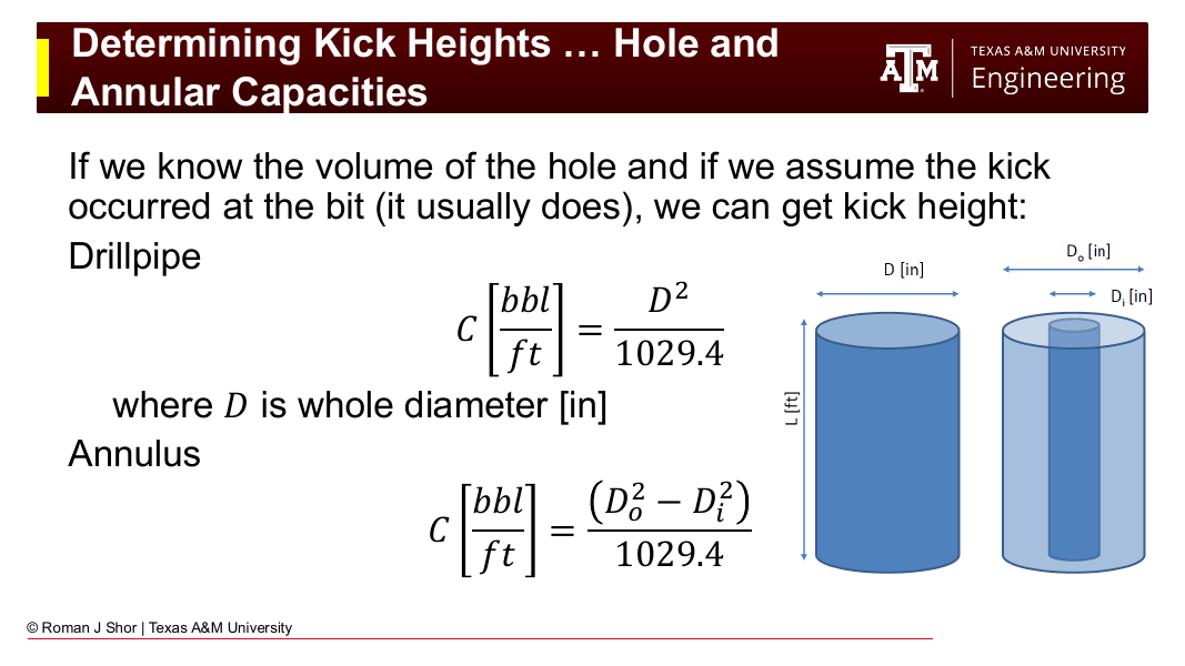
Fig. 126 Hole and annular capacities. Knowing the capacity (bbl/ft) of each wellbore section allows the kick volume measured at surface to be converted to a kick height at the bottom of the well.#
9.3 The Kill Sheet#
The kill sheet is a standardized form used to organize all necessary data and wellbore configuration details, and to pre-calculate the pressures and pump stroke counts needed to execute a kill operation. Completing the kill sheet before circulating out a kick is not optional — attempting a kill without it risks applying incorrect pressures and making the situation worse.
Key Term
The kill sheet is a pre-calculated reference document completed at shut-in that organizes all well data, kick data, and required kill pressures into a single document used by the driller and company man throughout the kill operation.
A standard kill sheet contains the following sections:
9.3.1 Well Data (Pre-Populated Before Drilling)#
These values are known before the kick occurs and are filled in during normal drilling operations:
Item |
Symbol |
Value |
|---|---|---|
Current mud weight |
\(\rho_\text{mud}\) |
ppg |
Total depth (MD) |
TD |
ft |
True vertical depth |
TVD |
ft |
Drill string capacity (drill pipe) |
\(V_\text{dp}\) |
bbl/ft |
Drill string capacity (drill collars) |
\(V_\text{dc}\) |
bbl/ft |
Total drill string internal volume |
\(V_\text{ds}\) |
bbl |
Pump output |
\(q\) |
bbl/stroke |
Strokes to displace drill string |
\(N_\text{ds}\) |
strokes |
Annular volume capacity (collars to shoe) |
— |
bbl/ft |
Annular volume capacity (pipe to shoe) |
— |
bbl/ft |
Annular volume capacity (BHA to pipe) |
— |
bbl/ft |
Total annular volume |
\(V_\text{ann}\) |
bbl |
Strokes to displace annulus |
\(N_\text{ann}\) |
strokes |
Slow circulating rate pressure |
SCR |
psi at — spm |
9.3.2 Kick Data (Filled In at Shut-In)#
These values are read or calculated immediately after shut-in:
Item |
Symbol |
Value |
|---|---|---|
Shut-in drill pipe pressure |
SIDPP |
psi |
Shut-in casing pressure |
SICP |
psi |
Pit gain (kick volume) |
\(V_\text{kick}\) |
bbl |
9.3.3 Calculated Kill Parameters#
From the kick data and well data, the following are calculated:
Kill mud weight: $\(\rho_\text{kill} = \rho_\text{mud} + \frac{\text{SIDPP}}{0.052 \times \text{TVD}}\)$
Kick height in annulus (assuming kick fills the annulus above the bit): $\(H_\text{kick} = \frac{V_\text{kick}}{C_\text{ann}}\)$
where \(C_\text{ann}\) is the annular capacity (bbl/ft) at the bottom of the well.
Kick density (identifies kick fluid type): $\(\rho_\text{kick} = \rho_\text{mud} - \frac{(\text{SICP} - \text{SIDPP})}{0.052 \times H_\text{kick}}\)$
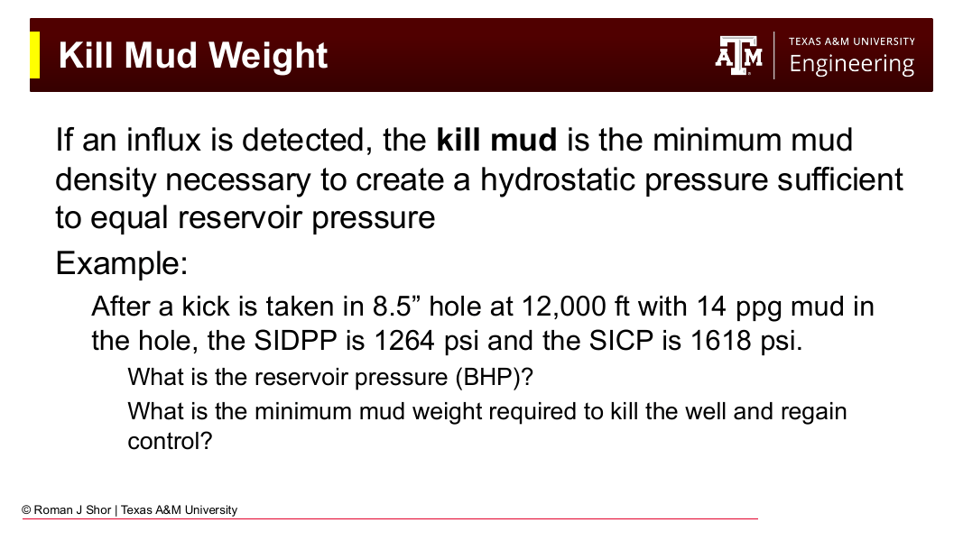
Fig. 127 Kill mud weight: the minimum mud density whose hydrostatic column balances the formation pressure revealed by the shut-in drill pipe pressure.#
Maximum allowable annular surface pressure (MAASP): $\(\text{MAASP} = (\text{LOT}_\text{EMW} - \rho_\text{mud}) \times 0.052 \times \text{TVD}_\text{shoe}\)$
Initial circulating pressure (ICP): $\(\text{ICP} = \text{SIDPP} + \text{SCR pressure}\)$
Final circulating pressure (FCP): $\(\text{FCP} = \frac{\rho_\text{kill}}{\rho_\text{mud}} \times \text{SCR pressure}\)$
These calculations are covered in detail in Chapter 10.
9.3.4 The Choke Pressure Schedule (Wait-and-Weight Method)#
For the Wait-and-Weight Method, the kill mud is mixed and then circulated in a single pass. As kill mud displaces the original mud in the drill string, the hydrostatic pressure at the bit gradually increases. To maintain constant bottomhole pressure, the choke pressure must be reduced in a controlled schedule as kill mud fills the drill string.
The choke pressure schedule is a table of choke pressure vs. pump strokes from the start of circulation:
Strokes pumped |
Kill mud in drill string (bbl) |
Required choke pressure (psi) |
|---|---|---|
0 |
0 |
ICP |
\(N_\text{ds}/4\) |
25% full |
— |
\(N_\text{ds}/2\) |
50% full |
— |
\(3N_\text{ds}/4\) |
75% full |
— |
\(N_\text{ds}\) |
100% (kill mud at bit) |
FCP |
Between ICP and FCP, the required choke pressure decreases linearly with strokes pumped. This schedule gives the driller a target to maintain, if the observed casing pressure matches the schedule, bottomhole pressure is being held constant.
The detailed construction of the choke schedule is covered in Chapter 10.
9.4 Shut-In Procedures#
The shut-in sequence is the critical bridge between detecting a kick and beginning a controlled kill operation. The key steps are:
Detect the kick. Flow check, pit gain observation, or flow alarm trigger.
Raise the kelly/top drive off bottom if rotating — space out so a tool joint is not across the BOP.
Pick up off bottom. Stop rotation and forward pump.
Close the BOP. For soft shut-in: open the choke first, then close the annular preventer, then close the choke. For hard shut-in: close the annular preventer immediately with the choke closed.
Record shut-in pressures. Allow pressures to stabilize. Record SIDPP and SICP.
Record pit gain. Read the trip tank or pit gain indicator.
Complete the kill sheet before any further action.
9.4.1 Kick Indicators#
Recognizing a kick in progress requires monitoring several simultaneous signals. Drilling rigs produce a continuous stream of data, and the driller is trained to respond when these indicators change unexpectedly.
Flow rate increase. The most definitive indicator: formation fluid entering the well displaces mud, increasing the return flow rate at surface. Rigs monitor this with a return-line flow sensor, typically a paddle-style flapper that measures mud returning through the return line. This sensor is notoriously imprecise; changes of only a few barrels may not register. More accurately, the driller monitors the trip tank, a small dedicated mud tank that collects returns. A rising level in the trip tank while the pump rate is unchanged indicates fluid gain from the formation. Modern rigs equipped with a Coriolis flow meter (common when managed pressure drilling equipment is installed) can detect a kick within 2–5 barrels. Without flow metering, a driller may not detect a kick until 20+ barrels have entered the well.
Pit volume gain. Related to flow rate, the total mud pit volume increases as formation fluid enters the well. An automatic pit-level alarm is a standard safety feature, but it responds more slowly than a trip-tank or Coriolis meter.
Rate of penetration (ROP) increase. An overpressured formation pushes cuttings off the bit face, reducing chip hold-down and increasing ROP. A sudden, unexplained ROP increase in a zone not expected to be soft is a warning sign. It is not conclusive on its own, a lithology change to a softer formation produces the same effect, but combined with other indicators it warrants a flow check.
Pump pressure change. Inflow from a high-pressure zone slightly increases the annular pressure against which the pump is working. The change is usually subtle and may not be noticed before other indicators are apparent.
Flow after pump-off (connection gas). During a pipe connection, when the pump is shut off and drill pipe is being made up, a small flow out of the well when the pump is off is a definitive indicator of underbalance. This is called a connection kick or connection flow check and should always be performed by shutting the pumps off briefly and watching for return flow.
9.4.2 Soft vs. Hard Shut-In#
When a kick is detected, the well is shut in by closing the BOP. Two philosophies exist for the sequencing:
Hard shut-in closes the BOP (annular preventer or pipe rams) immediately with the choke closed. This is fast and simple, but creates a brief surge of pressure at the BOP as flow is abruptly stopped. Industry practice has largely moved to hard shut-in for most situations because the simplicity reduces the chance of procedural error under stress, and the pressure surge is usually short-lived and within equipment ratings. However, MAASP may be temporarily exceeded and the open hole section of the well is stressed by the pressure surge.
Soft shut-in first opens the choke (diverting flow through the choke manifold), then closes the BOP, then slowly closes the choke. This was originally preferred to protect BOP equipment from water-hammer pressure spikes. Modern BOPs are designed to handle hard shut-in pressures, and soft shut-in carries the risk of allowing additional influx to enter the well during the additional time the choke is open.
In both cases, the outcome is the same: the well is closed and pressures stabilize. Hard shut-in is now the recommended default for most applications.
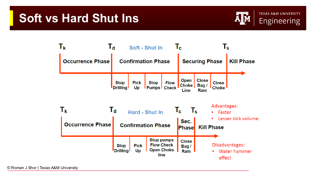
Fig. 128 Soft vs. hard shut-in timelines. The hard shut-in reaches the secured state faster and takes a smaller kick volume, at the cost of a water-hammer pressure surge as flow is abruptly stopped.#
9.4.3 Tripping Operations#
Kicks taken while tripping (pulling the drill string out of the hole) present additional complications:
Reduced hydrostatic column. As pipe is pulled, the mud column height decreases, which can reduce bottomhole pressure below pore pressure, especially when the pipe is pulled too fast (swabbing) or without filling the hole with mud.
Partially out-of-hole string. The drill string may be partly removed, with the bit somewhere above bottom. A standard kill circulation is not possible if the bit is not at or near bottom.
String inside casing. If the string is pulled above the casing shoe, the string cannot be run back to a formation kick zone without running into open hole.
Response: If a kick is taken on a trip, the driller should run the string back to bottom (if safe to do so) before attempting a kill circulation. The trip tank should be monitored continuously while tripping, and the hole should be filled with mud after every stand pulled. If the string cannot be run to bottom, the volumetric method (Section 9.5.3) or bullheading (Section 9.7.3) may be required as alternatives to a standard kill circulation.
9.5 Kill Methods: Operational Detail#
9.5.1 Driller’s Method#
The Driller’s Method uses two complete circulations. Its key advantage is that it can begin immediately after shut-in, without waiting for kill mud to be mixed. The mud engineer works on the kill mud simultaneously while the driller begins circulating out the kick.
First circulation — circulate out the kick:
The driller starts the pump at kill rate (slow pump rate). The moment the pump reaches kill speed, drill pipe pressure rises from SIDPP to ICP (= SIDPP + SCR). The choke is adjusted to hold drill pipe pressure constant at ICP throughout the first circulation. Holding drill pipe pressure constant at ICP ensures that bottomhole pressure remains constant at formation pressure, because the hydrostatic contribution from original mud in the drill string has not changed.
Meanwhile, the kick fluid in the annulus migrates upward and is displaced toward surface. The choke operator watches drill pipe pressure (not casing pressure) and adjusts the choke to hold it at ICP. For a gas kick, casing pressure rises during this phase as the gas expands, the choke operator must open the choke progressively to prevent casing pressure from exceeding MAASP. When the kick exits through the choke and is processed by the choke manifold and gas-separation equipment, casing pressure drops back. At the end of the first circulation, the kick has been fully removed and casing pressure stabilizes at or near SIDPP.
Second circulation — pump kill mud:
Kill mud (pre-weighted to kill weight) is pumped down the drill string. As kill mud fills the drill string, the drill string hydrostatic increases progressively, and less surface pressure is required to maintain BHP at formation pressure. Drill pipe pressure decreases linearly from ICP (when pumping starts) to FCP (when kill mud reaches the bit). The choke is slowly closed as kill mud fills the string — following the same linear pressure schedule used in the Wait-and-Weight Method. After kill mud reaches the bit and the entire drill string is displaced, drill pipe pressure holds at FCP. As kill mud fills the annulus and replaces the original mud, casing pressure decreases to zero. When kill mud appears at the choke outlet, the well is dead and the pump can be shut down.
Driller’s Method Summary
First circulation: Hold drill pipe pressure at ICP. Circulate kick out with original mud. Gas rises and expands — choke opens to vent it while holding drill pipe pressure constant.
Second circulation: Pump kill mud. Drill pipe pressure decreases linearly from ICP to FCP as kill mud fills the drill string. Hold FCP until kill mud fills the annulus. Well is dead when kill mud reaches the choke.
Advantages: Kick removal begins immediately. The mud engineer can mix kill mud at their own pace.
Disadvantages: The kick reaches surface during the first circulation, requiring careful gas handling. Two circulations mean more total time at well-control conditions.
9.5.2 Wait-and-Weight Method#
The Wait-and-Weight Method uses a single circulation. Kill mud is weighted up to kill weight and mixed before any circulation begins.
Preparation: After shut-in and kill sheet completion, the mud engineer begins mixing kill mud immediately by adding weighting material (barite) to the active pit. This typically requires 1–4 hours, depending on pit system capacity, available barite, and the required density increase. The well remains shut in during this period.
Single circulation: Once kill mud is ready, the pump is started at kill rate and drill pipe pressure is brought up to ICP. Kill mud is pumped down the drill string while original mud (and the kick) remains in the annulus. As kill mud progressively fills the drill string, the hydrostatic increases and the choke is closed down, following the choke pressure schedule exactly, linearly reducing drill pipe pressure from ICP to FCP over \(N_\text{ds}\) strokes. When kill mud reaches the bit, drill pipe pressure has reached FCP and holds there.
As kill mud enters the annulus from the bit, it displaces the original mud and kick fluid upward. The heavier kill mud at the bottom of the annulus provides increasing hydrostatic support. Casing pressure decreases as kill mud fills the annulus from bottom to top. When kill mud appears at the choke, the well is dead.
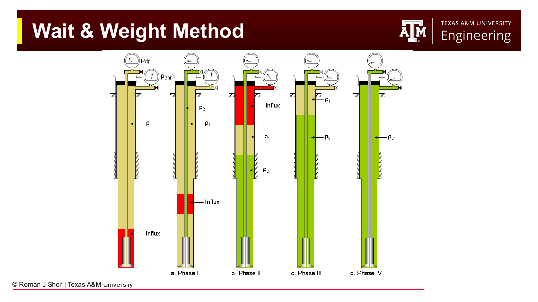
Fig. 129 The Wait-and-Weight Method phase by phase: influx at bottom (left), kill mud (\(\rho_2\)) displacing the drill string (Phase I), influx circulated up the annulus (Phase II), kill mud filling the annulus (Phase III), and the dead well fully displaced to kill mud (Phase IV).#
Wait-and-Weight Summary
Preparation: Mix kill mud before starting. May take 1–4 hours.
Single circulation: Follow choke pressure schedule exactly — ICP at start, linear decrease to FCP as kill mud fills the drill string, hold FCP while kill mud fills the annulus. Well is dead when kill mud reaches choke.
Advantages: Only one circulation; kill mud enters the annulus immediately after the bit, reducing the maximum pressure at the shoe (compared to the first Driller’s Method circulation with a gas kick). The well is under better pressure control throughout.
Disadvantages: Must wait for kill mud to be prepared before starting any circulation. Requires strict adherence to the choke pressure schedule throughout.
Driller’s Method vs. Wait-and-Weight: The fundamental difference is timing. Driller’s Method says “get the kick out now and mix the mud on the side.” Wait-and-Weight says “mix the mud first, then circulate once and kill the well.” For a gas kick with a narrow drilling window (low MAASP), Wait-and-Weight is generally preferred because the kill mud in the drill string from the start of circulation provides progressively increasing bottomhole pressure, reducing the chance of fracturing the shoe. For a liquid kick in a well with ample MAASP margin, the Driller’s Method’s speed advantage may be preferred.
9.5.3 Volumetric Method#
The volumetric method is used when the drill string is not at bottom and a circulation-based kill cannot be performed. It does not kill the well: it controls gas migration to surface in a safe, stepwise manner. It is a temporary emergency procedure, used until the string can be run back to bottom for a conventional kill.
Background: When a gas kick is shut in, the gas migrates upward through the mud column due to buoyancy. If the well is simply shut in, the gas rises at constant volume and pressure builds at both the drill pipe gauge and the casing gauge. Eventually surface pressures will exceed MAASP and fracture the shoe. The volumetric method controls this migration by deliberately bleeding fluid from the annulus in small, calculated increments — allowing the gas to expand and rise while maintaining a minimum safety pressure above the kick.
Procedure:
Determine the safety margin: a small positive pressure (typically 100–200 psi) maintained above the kick to ensure the gas does not expand uncontrolled.
Allow surface pressure to build by the safety margin as gas migrates upward (constant-volume migration raises casing pressure).
Bleed a small, calculated volume of mud from the annulus — enough to allow the gas to expand and drop casing pressure back to the original safety margin level, while maintaining the same bottomhole pressure.
Record the mud volume bled and repeat.
The mud volume to bleed per step is calculated from the target pressure drop and the annular capacity. The process is repeated until the gas kick has migrated to a depth where a conventional kill can be performed.
Key Concept
The volumetric method trades mud volume for surface pressure in a controlled, stepwise fashion. It does not kill the well — it manages gas migration to surface while preserving wellbore integrity, until a conventional kill method can be applied.
9.6 Gas Behavior During Kill Operations#
Gas kicks present unique challenges compared to liquid kicks because gas is compressible. Its volume, and therefore its height in the annulus, changes as it migrates to lower pressures during a kill operation.
9.6.1 Gas Migration#
When a well is shut in with gas in the annulus, gas migrates upward through the mud column due to buoyancy, even with no circulation. This is the key difference between a gas kick and an oil or water kick: liquid kicks do not migrate appreciably.
Gas migration at constant wellbore volume (shut-in) raises the pressure at both gauges equally. If SIDPP and SICP both rise at the same rate after shut-in with no pumping, gas migration is occurring. This can cause surface pressures to approach MAASP and fracture the casing shoe, releasing the kick into a shallower formation (an underground blowout).
To manage gas migration in a shut-in well, the volumetric method (Section 9.5.3) is used.
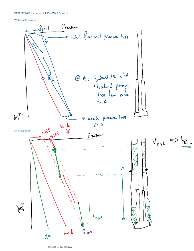
Fig. 130 Instructor’s worked notes on wellbore pressures and kick migration: as the shut-in gas kick migrates upward without expanding, it carries its pressure with it, raising SIDPP and SICP together (from PETE 355 lecture notes).#
9.6.2 Gas Expansion During Circulation#
As gas rises during a kill circulation, the pressure above the gas decreases. By the ideal gas law (or more accurately, the real gas law), the volume of the gas increases:
As the gas expands, it occupies a taller column in the annulus. This means:
The choke must be progressively opened to allow expanding gas to exit, or casing pressure will rise rapidly.
The choke operator controls drill pipe pressure (not casing pressure) — casing pressure is allowed to rise and fall as the gas expands.
Gas kicks expand most dramatically near surface, where pressures are lowest. The gas height is maximum when the top of the kick first arrives at the choke outlet.
Using the real gas law (with a Z-factor) gives the actual expansion, which is generally less than predicted by the ideal gas law. For conservative (worst-case) surface pressure estimates, the ideal gas law is used.
9.6.3 Gas Solubility and Bubble Point#
At high bottomhole pressures, some gas dissolves in the oil phase of the drilling fluid. As the gas-laden fluid rises and pressure decreases, it reaches its bubble point — the pressure at which dissolved gas starts to come out of solution. Below the bubble point, gas bubbles form and expand, effectively increasing the gas volume in the annulus above what was observed at the kick depth.
This is a particular concern for oil-based mud (OBM) systems, which can dissolve large volumes of gas without immediate surface evidence. An OBM gas kick may show minimal pit gain at bottom but significant expansion as it rises through the bubble point depth. Kill operations in OBM must account for this dissolved-gas effect.
9.6.4 Underground Blowout#
If casing pressure exceeds MAASP during a kill operation, the formation at the casing shoe fractures. The kick fluid, instead of continuing to surface, diverts into the fracture and flows downward or laterally into the fractured formation. This is an underground blowout: fluid flows from a high-pressure formation at the bottom into a weaker formation at the shoe. The well loses returns but the kick does not reach surface, it flows from one formation into another underground.
Underground blowouts are difficult to detect and control. Indicators include a sudden drop in casing pressure (fracture takes the pressure), total loss of returns at surface, and possible heave or subsidence at surface. Response options include allowing the underground blowout to self-kill (if the receiving formation has enough storage capacity), drilling a relief well, or applying surface pressure to force kill fluid into the formation.
9.7 Special Situations#
9.7.1 Horizontal Well Considerations#
Horizontal wells introduce complications not present in vertical wells:
TVD vs. MD. Hydrostatic pressure depends on true vertical depth (TVD), while pump stroke counting uses measured depth (MD). In a well that goes 5,000 ft TVD and then 15,000 ft horizontally, the MD is 20,000 ft but the hydrostatic column is set by TVD. Kill mud weight must be calculated from TVD; stroke counts to displace the drill string and annulus must use MD.
Kick stratification. In a horizontal wellbore, gas and liquid phases separate: gas accumulates on the high side of the wellbore, oil/water on the low side. This non-uniform distribution complicates the hydrostatic calculation because the effective kick gradient depends on the degree of stratification. Sophisticated multi-phase models are used in practice; simplified well control methods may under- or overestimate surface pressures.
Large annular volumes. Long horizontal sections have very large annular volumes. A kick can grow to hundreds of barrels before significant pit gain is registered at surface, especially with a flapper-style flow meter. The MPD flow monitoring equipment described in Chapter 19 is particularly valuable in horizontal wells for early kick detection.
Casing shoe considerations. The critical casing shoe for MAASP purposes is at the end of the vertical or build section, not at total depth. The kick must be brought through the entire horizontal section before reaching the shoe depth, and casing pressure must be managed throughout.
9.7.2 Deepwater Well Control#
Deepwater wells present some of the most challenging well control environments:
Narrow drilling window. Deepwater formations often have pore pressures and fracture gradients that are very close together, sometimes less than 0.5 ppg window. There is little margin for mud weight error, and a small kick may require a kill mud weight that approaches or exceeds the fracture gradient at the shoe.
Riser and subsea BOP. The BOP stack is located on the seafloor, not at the rig. The riser, the large conduit connecting the BOP to the drilling rig, contains a column of drilling mud that provides hydrostatic pressure over the water column. If the riser is deliberately disconnected in an emergency (riser disconnect), the hydrostatic column is lost and bottomhole pressure may drop below pore pressure. The riser margin is the additional mud weight required to account for a possible riser disconnect scenario.
Hydrate formation. In deepwater, the combination of low temperatures and high pressures creates thermodynamic conditions where natural gas and water form a solid crystalline structure called a hydrate. Hydrates can plug the BOP, choke, and kill lines, preventing shut-in and kill operations. Thermodynamic inhibitors (methanol, glycol) are injected into critical lines during kill operations to prevent hydrate formation.
Kill line friction. Long, small-diameter kill and choke lines from the surface to the subsea BOP introduce significant friction pressure. This friction must be accounted for in all pressure calculations — the standpipe pressure at surface may not accurately represent the annular pressure at the BOP.
Managed pressure drilling was developed in part as a response to the challenges of drilling narrow-window deepwater formations.
9.7.3 Barite Plugs and Bullheading#
When conventional circulation-based kill methods are not feasible, two alternative techniques are available:
Bullheading involves pumping kill fluid (or formation fluid back into the formation) directly down the annulus from surface, with the intention of forcing the kick fluid back into the formation under high pressure. It is used when:
The drill string is off bottom or partially out of the hole and cannot be run back.
The kick fluid composition is dangerous (H₂S) and bringing it to surface is unacceptable.
The formation is permeable enough to accept injected fluid.
Bullheading requires pumping at rates and pressures that may exceed the formation fracture pressure at the kick zone, so it requires careful engineering. If the kick fluid cannot be forced back into the formation fast enough, surface pressures may spike. Of note, the kick will go into the lowest pressure formation in the open hole, and may not go back into the formation from which it came. This can lead to increases in pressure in other zones. In 2009, a kick into a geothermal well being drilled in Basel, Switzerland, caused a magnitude 3.4 earthquake when being bullheaded back into the formation, leading to a complete moratorium on geothermal drilling in the city that continues to this day.
Barite plugs are dense, cement-like slurries of barite (BaSO₄) mixed with water and possibly additives, pumped into the wellbore to create a dense hydrostatic plug above the kick zone. The extreme density of barite (specific gravity ≈ 4.2) allows a relatively short plug to generate large hydrostatic pressure. Barite plugs are a last resort used when all other methods have failed and a permanent seal above the kick zone is required. They are difficult to remove if the plug sets prematurely or in the wrong location.
9.8 Practice Problems#
Problem 9.1 — Shut-In Sequence. A driller notices the trip tank gaining volume while drilling at 11,500 ft TVD. Describe the complete shut-in sequence step by step, starting from the decision to shut in. What does “space out” mean, and why is it done before closing the BOP?
Solution
Stop rotation and raise off bottom.
Space out — pull the drill string until no tool joint (connection) lies within the BOP stack. Tool joints have a larger outer diameter than the pipe body, and pipe rams cannot seal properly on a joint. A shear ram can cut through a joint but this sacrifices the drill string.
Shut off the mud pump.
Close the annular BOP or pipe ram (a hard shut-in — close BOP directly without opening choke first).
Close the choke.
Read and record SIDPP (stabilized standpipe gauge) and SICP (stabilized casing/annular gauge).
Read and record pit gain (trip tank volume increase).
Notify the company man / rig supervisor.
Complete the kill sheet before any circulation is started.
Problem 9.2 — Kill Method Selection. A well is shut in at 12,000 ft TVD with SIDPP = 450 psi, SICP = 720 psi, pit gain = 20 bbl, mud weight = 12.0 ppg, and casing shoe at 8,000 ft TVD with LOT EMW = 15.5 ppg. SCR pressure = 700 psi.
(a) Calculate kill mud weight.
(b) Calculate MAASP.
(c) Is there margin to safely perform either kill method?
(d) For the Driller’s Method, what is the target drill pipe pressure during the first circulation?
Solution
(a) Kill mud weight: $\(\rho_\text{kill} = 12.0 + \frac{450}{0.052 \times 12000} = 12.0 + 0.72 = 12.72 \approx 12.8 \text{ ppg}\)$
(b) MAASP: $\(\text{MAASP} = (15.5 - 12.0) \times 0.052 \times 8000 = 3.5 \times 0.052 \times 8000 = 1456 \text{ psi}\)$
(c) ICP = 450 + 700 = 1150 psi. SICP = 720 psi. Both are well below MAASP = 1456 psi. ✓ There is comfortable margin for either method.
(d) In the Driller’s Method first circulation, the target drill pipe pressure is ICP = 1150 psi throughout.
Problem 9.3 — Gas Migration. A well is shut in with SIDPP = 350 psi and SICP = 550 psi. After 2 hours with no pumping, SIDPP has risen to 500 psi and SICP has risen to 700 psi. What is happening and what are the implications?
Solution
Both SIDPP and SICP have risen by 150 psi. When both gauges increase at the same rate with no pumping, gas is migrating upward through the mud column at constant volume. The rising gas causes pressure to build throughout the closed system equally.
If this continues unchecked, surface pressures will eventually exceed MAASP and fracture the casing shoe. The operator must either begin a kill circulation or apply the volumetric method — bleeding small volumes of mud to allow controlled gas expansion while maintaining bottomhole pressure at formation pressure.
Problem 9.4 — Bullheading Decision. During a trip, the drill string is pulled to the point where the bit is 3,000 ft above bottom. The well kicks. The kick is identified as H₂S-bearing gas. Describe why a conventional kill circulation is not possible and what alternatives should be considered.
Solution
A conventional kill circulation requires the bit to be at or near bottom so that kill mud can be pumped through the bit and fill the annulus from below. With the bit 3,000 ft off bottom, pumping down the drill string would push kill mud into an open-hole annulus above the kick zone — not through the kick zone itself. The kick cannot be circulated out.
Alternatives:
Run the string back to bottom — if the kick is not too large and wellbore conditions permit, running the string back while monitoring and managing casing pressure may be possible. This restores the ability to perform a conventional kill.
Bullheading — pump H₂S-bearing fluid back down the annulus and into the formation under high pressure. Preferred here because bringing H₂S to surface is extremely dangerous to personnel. Requires the formation to be permeable enough to accept injected fluid.
Volumetric method — if the string cannot be run back and bullheading is not possible, the volumetric method may be used to manage gas migration to surface, but it does not eliminate the H₂S hazard at surface. In practice for H₂S kicks, bullheading is strongly preferred to avoid exposing rig crew to toxic gas at surface.
Chapter Summary#
Well control is not improvised under pressure, it is executed according to pre-calculated procedures organized in the kill sheet. The key pre-kick information (SCR pressure, pump output, wellbore volumes) must be current and accurate. At shut-in, SIDPP and SICP are read and used to calculate kill mud weight, kick properties, and the pressure schedule for the chosen kill method.
The kill sheet connects the shut-in observations to the kill operation: it computes ICP, FCP, and the choke schedule before the pump is started. Chapter 10 develops the calculations behind each entry in the kill sheet.
Key Equations#
Quantity |
Formula |
|---|---|
Kill mud weight |
\(\rho_\text{kill} = \rho_\text{mud} + \dfrac{\text{SIDPP}}{0.052 \times \text{TVD}}\) |
Kick height |
\(H_\text{kick} = V_\text{kick} / C_\text{ann}\) |
Kick density |
\(\rho_\text{kick} = \rho_\text{mud} - \dfrac{\text{SICP} - \text{SIDPP}}{0.052 \times H_\text{kick}}\) |
MAASP |
\(\text{MAASP} = (\text{LOT}_\text{EMW} - \rho_\text{mud}) \times 0.052 \times \text{TVD}_\text{shoe}\) |
Initial circulating pressure |
\(\text{ICP} = \text{SIDPP} + \text{SCR}\) |
Final circulating pressure |
\(\text{FCP} = \dfrac{\rho_\text{kill}}{\rho_\text{mud}} \times \text{SCR}\) |