
Chapter 4: Drilling Fluids#
Learning Objectives#
By the end of this chapter, you will be able to:
Describe the primary functions of a drilling fluid and explain why each is essential to safe drilling operations
Identify the causes of loss of well control and explain how the drilling fluid acts as the primary barrier against a blowout
Classify drilling fluids by base fluid type and describe the principal ingredients and characteristics of each class
Compare water-based, oil-based, and synthetic-based mud systems in terms of composition, performance, and environmental considerations
Explain the role of the filter cake and how fluid loss is controlled
Discuss the factors that guide mud system selection for a given well
4.1 Introduction: Why Drilling Fluids Matter#
Of all the systems on a drilling rig, drilling fluids are perhaps the most overlooked — and the most consequential. The fluid circulating through the wellbore is doing far more than simply cooling the drill bit. It is the primary barrier keeping the well from blowing out. It is transporting tons of rock cuttings from kilometers underground to the surface. It is stabilizing the walls of an open hole that could otherwise collapse. And in directional wells, it provides much of the hydraulic power to the mud motor to keep drilling ahead.
Consider what happens when you pick up a glass of water you cannot see into: you’ve handled water before, so you instantly know from the weight that the glass is full. A petroleum engineer needs the same intuition about drilling fluids — what does 10 ppg (lb/gal) mud feel like compared to 14 ppg? What does a fluid with high gel strength do when the pumps stop? These are not abstract questions; the answers directly affect whether a well is drilled safely and economically.
This chapter introduces the history, functions, types, and composition of drilling fluids. Chapter 5 covers how fluid properties are measured and characterized, and Chapter 6 covers the calculations used to design and modify mud systems.
4.2 History and Development of Drilling Fluids#
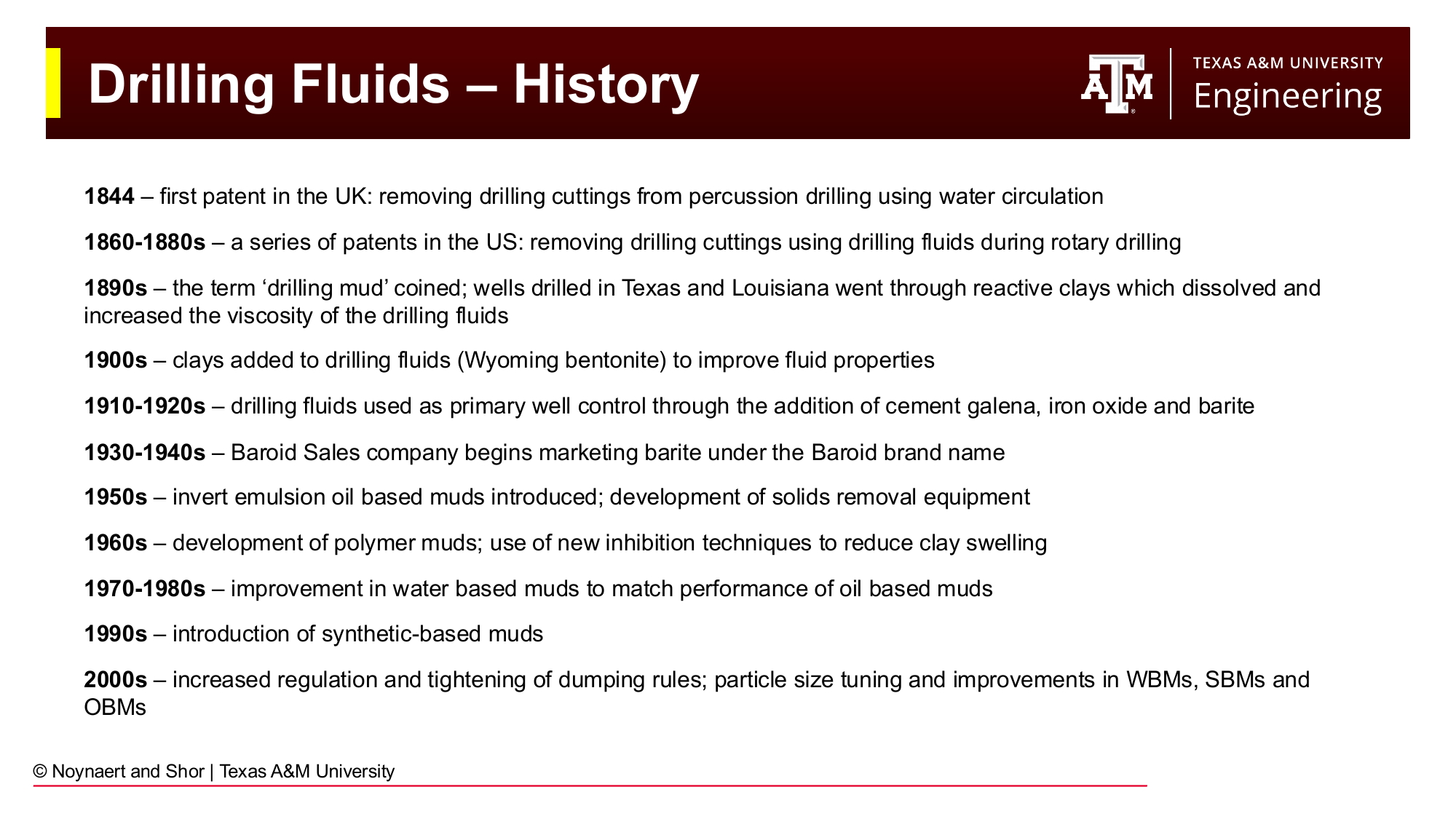
Fig. 34 Key milestones in the development of drilling fluids, from the first use of water circulation for cuttings removal to modern synthetic-based muds.#
The use of circulating fluid to remove cuttings from a borehole dates to the earliest days of rotary drilling:
1844 — The first patent related to drilling fluid was granted in the UK, describing the use of water circulation to remove cuttings from percussion drilling. (British Patent No. 10,258, granted 1845)
1860–1880s — A series of US patents extended the concept to rotary drilling, recognizing that circulating fluid was essential for continuous drilling progress.
1890s — The term “drilling mud” was coined when drillers in Texas and Louisiana noticed that wells drilled through reactive clay formations produced a naturally viscous, mud-like fluid that actually improved hole stability. The dissolving clay was acting as a viscosifier.
1900s — Wyoming bentonite was deliberately added to drilling fluids to improve viscosity and hole stability — the first engineered mud additive.
1910–1920s — The added benefit of well control while utilizing drilling fluid was recognized. Heavy materials including cement, galena (lead sulfide), iron oxide, and barite were added to increase mud density and counterbalance formation pressures.
1930–1940s — Barite became the standard weighting material. The Baroid Sales Company (later Baker Hughes) began marketing barite commercially, formalizing the drilling fluids industry.
1950s — Invert emulsion oil-based muds (OBMs) were introduced for drilling difficult shale formations. Solids removal equipment (shale shakers) was developed to manage cuttings more efficiently.
1960s — Polymer muds were developed, offering an alternative to clay-based systems with better inhibition of clay swelling.
1970–1980s — Significant improvements in water-based mud chemistry brought WBM performance closer to that of OBMs in many applications.
1990s — Synthetic-based muds (SBMs) were introduced as an environmentally acceptable alternative to diesel-based OBMs for offshore deepwater applications.
2000s onward — Tightening environmental regulations drove further development of high-performance water-based muds (HPWBMs), improved particle size tuning, and better solids control equipment.
4.3 Functions of Drilling Fluids#
Drilling fluid must simultaneously perform multiple functions, some of which place competing demands on its properties. The mud engineer’s job is to maintain a fluid system that satisfies all these requirements throughout the drilling operation.
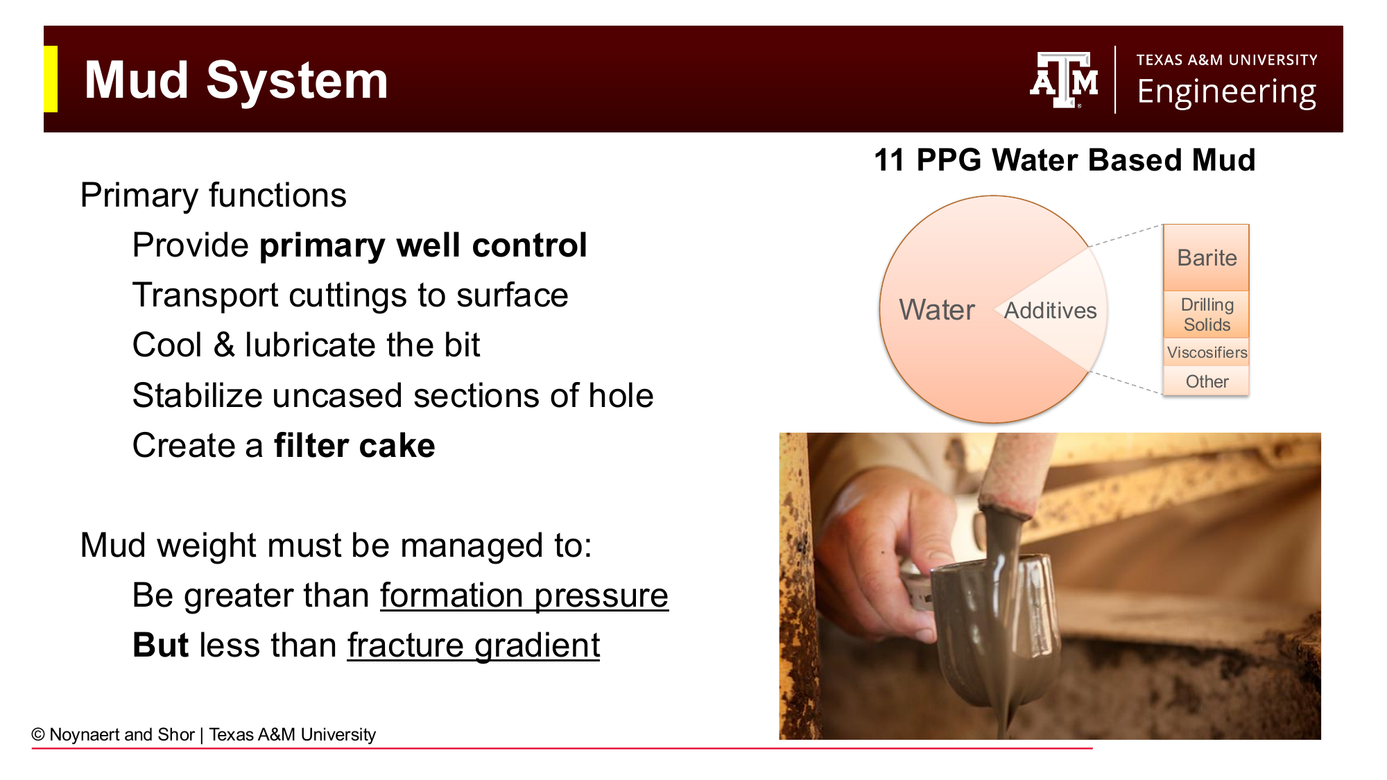
Fig. 35 The primary functions of a drilling fluid and a schematic of the typical composition of an 11 ppg water-based mud. The fluid must simultaneously provide well control, transport cuttings, stabilize the hole, and cool the bit.#
4.3.1 Primary Well Control#
The single most important function of the drilling fluid is to maintain a hydrostatic pressure greater than the formation pore pressure at all points in the open hole. This overbalance prevents formation fluids (oil, gas, or brine) from flowing into the wellbore, an event called a kick. If a kick is not detected and controlled, it can escalate into a blowout: an uncontrolled flow of formation fluids to the surface.
The hydrostatic pressure provided by the mud column is determined by the mud density (weight) and the true vertical depth of the fluid column. This relationship — explored in detail in Chapters 5 and 6, is the foundation of all mud weight design.
Key Term: Kick
A kick is an influx of formation fluid (gas, oil, or brine) into the wellbore, caused by wellbore pressure falling below formation pore pressure. Kicks are detected by increases in pit volume, changes in pump pressure, or gas returns at surface, and must be circulated out safely using well control procedures, otherwise they may become blowouts.
4.3.2 Hole Cleaning: Cuttings Transport#
As the drill bit destroys rock, the resulting cuttings must be lifted from the bit-rock interface and carried up the annulus (the space between the drill string and the borehole wall) to the surface. If cuttings accumulate in the annulus, the drill string can become stuck, one of the most common and expensive drilling problems.
Efficient cuttings transport requires:
Sufficient annular velocity (pump rate) to overcome the settling velocity of the cuttings
Adequate mud viscosity to suspend cuttings, especially when circulation is interrupted
Appropriate gel strength to hold cuttings in suspension when the pumps are shut down
4.3.3 Borehole Stability#
In uncased sections, the wellbore is an open hole in rock. Many formations, particularly shales, tend to swell, slough, or collapse when exposed to drilling fluid. The mud must:
Provide sufficient hydrostatic pressure to support the borehole walls against mechanical collapse
Inhibit chemical interactions (particularly hydration and swelling of clay minerals) through its chemical composition
Minimize invasion of filtrate into the formation, which can weaken the near-wellbore rock by increasing near wellbore pore pressure
4.3.4 Cooling and Lubricating the Drill Bit and String#
Drilling generates significant heat from mechanical friction and rock destruction. The mud circulates continuously over the bit face, removing heat and preventing thermal damage to the bit cutting elements and downhole tools. It also lubricates the contact between the drill string and the borehole wall, reducing torque and drag, particularly important in directional and horizontal wells.
4.3.5 Filter Cake Formation#
When overbalanced mud contacts a permeable formation, the pressure differential drives filtrate (the liquid phase of the mud) into the rock. The solid particles in the mud are too large to enter the pores and accumulate at the wellbore face, forming a filter cake, a thin, low-permeability layer that progressively restricts further filtrate invasion. A well-engineered filter cake:
Is thin (minimizes reduction in borehole diameter)
Has low permeability (minimizes continued filtrate invasion)
Is tough (resists erosion by the flowing mud or with the rotating drillstring)
Has a low friction coefficient (allows easy pipe movement across it)
Is removeable, particularly in the production zones. Filter cake and other reductions in near wellbore permeability are called skin. Once a well is completed, skin factor should be as low as possible
Key Term: Filter Cake
A filter cake is a thin layer of mud solids that deposits on the face of a permeable formation when overbalanced mud is present. The filter cake is essential for limiting fluid loss into the formation and stabilizing the borehole wall. Its thickness is typically measured in units of 1/32 inch during API fluid loss tests. It should also be removeable to enable future production in the well.
4.3.6 Downhole Information Transmission#
Modern drill strings contain measurement-while-drilling (MWD) and logging-while-drilling (LWD) tools that transmit data to the surface. The most common transmission method is mud pulse telemetry: pressure pulses are generated in the mud column by a valve in the drill string and decoded at surface. The mud must have appropriate hydraulic properties to transmit these pulses clearly without excessive signal attenuation.
4.3.7 Formation Evaluation Support#
Cuttings returned to the surface in the mud stream are sampled and analyzed by the wellsite geologist to identify the formations being drilled and detect hydrocarbon shows. The mud must be designed so that the cuttings it carries are representative and undamaged: excessive chemical alteration of cuttings by the mud reduces their geological value.
4.4 Causes of Loss of Well Control#
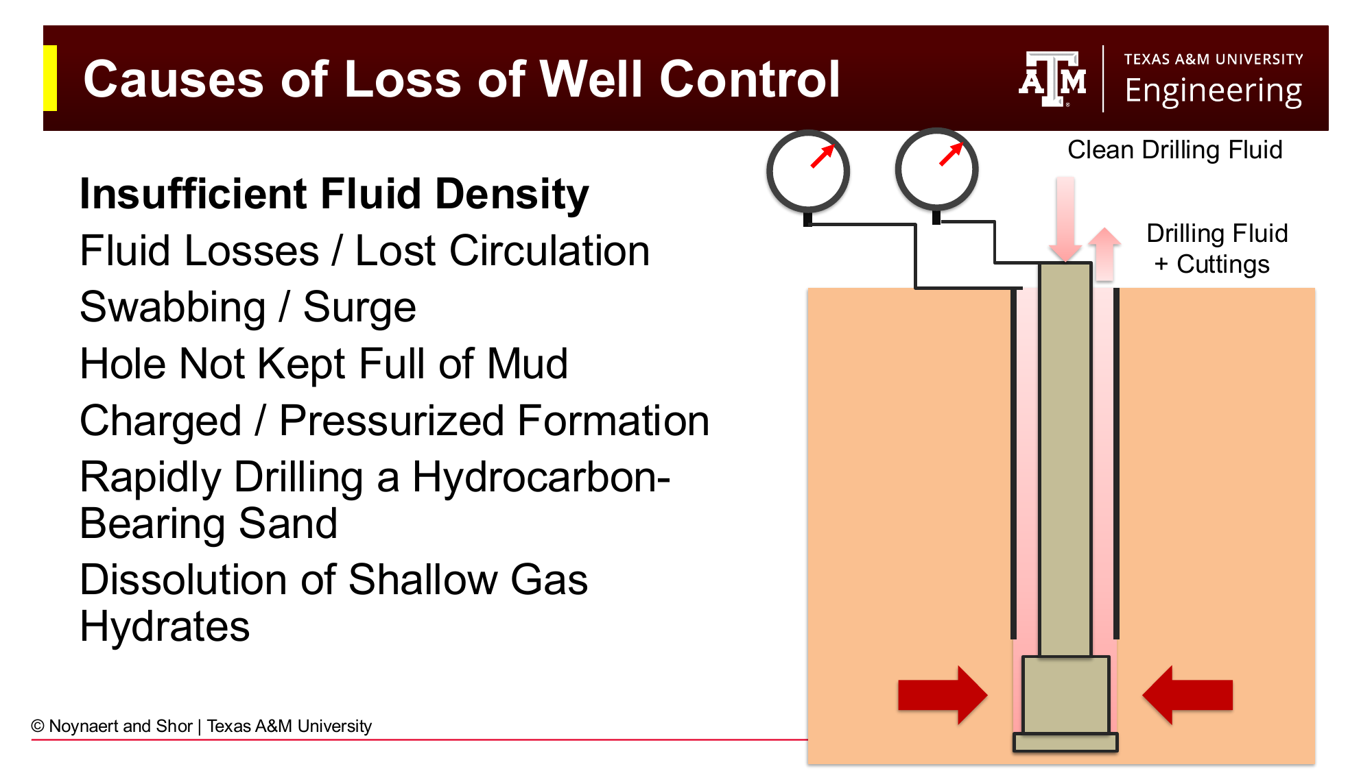
Fig. 36 The principal causes of loss of well control. Most involve some disruption to the hydrostatic pressure balance maintained by the drilling fluid.#
Loss of primary well control (a kick) can result from several causes, all of which share the common mechanism of wellbore pressure falling below formation pressure:
Insufficient mud density — The most direct cause: the mud is simply not heavy enough to counterbalance formation pore pressure. This can result from poor well planning (incorrect pore pressure prediction) or from dilution of the mud by formation fluids or water.
Fluid losses and lost circulation — When mud is lost into a highly permeable or fractured formation, referred to as lost circulation, the fluid level in the annulus drops, reducing the hydrostatic head. If the fluid level falls enough, the hydrostatic pressure can drop below pore pressure, allowing formation fluids to flow in from deeper zones.
Swabbing — When the drill string is pulled out of the hole, the upward movement creates a suction effect (negative surge pressure) in the annulus below the bit. If the surge is large enough, it temporarily reduces bottomhole pressure below pore pressure, inducing a kick. Swabbing is most problematic in narrow drilling windows (tight margin between pore pressure and fracture gradient).
Surging — The opposite of swabbing: running the drill string into the hole too quickly creates a positive pressure surge that can exceed the fracture gradient and cause lost circulation due to the propogation of fractures in the near wellbore region.
Hole not kept full — When tripping pipe out of the hole, the volume of steel being removed is replaced by mud flowing in. If the hole is not kept full of mud (through periodic pumping or filling of the annulus), the fluid level and hydrostatic pressure drop.
Charged or pressurized formations — In areas with nearby production, injection, or previous well operations, shallow formations may be at elevated pressure due to fluid migration from the subsurface. These “charged” zones are difficult to predict and can cause unexpected kicks.
Rapidly drilling a hydrocarbon-bearing sand — High rates of penetration through a porous gas-bearing formation can introduce a large volume of gas into the annulus very quickly, reducing the effective mud density (gas “cut” mud is less dense than uncontaminated mud).
Dissolution of shallow gas hydrates — In deepwater environments, methane hydrates (solid ice-like structures of gas and water) can be present in shallow sediments. If the temperature or pressure conditions change, hydrates can dissociate and release gas into the wellbore.
4.5 Barriers to Well Control#
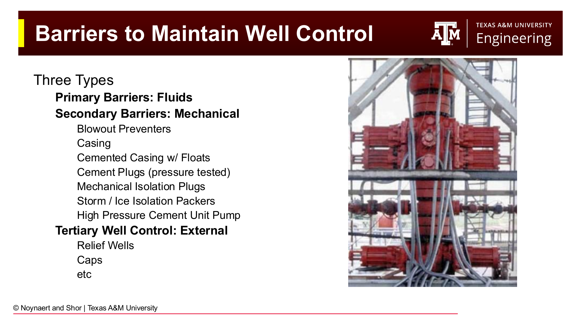
Fig. 37 The three tiers of well control barriers. The drilling fluid is the first and most important line of defense. Mechanical barriers (BOPs, casing, cement) are secondary. External measures (relief wells) are a last resort.#
Well control is maintained through a hierarchy of three barrier types:
Primary barriers — Fluids. The drilling fluid (mud) is always the first line of defense. As long as the mud weight is correctly maintained within the drilling window, formation fluids cannot enter the wellbore. The entire well control engineering effort is organized around maintaining this primary barrier.
Secondary barriers — Mechanical. If the primary barrier fails (a kick occurs), mechanical barriers prevent the kick from reaching surface or becoming a blowout. These include:
Blowout preventers (BOPs) — ram-type and annular preventers that can seal the wellbore
Casing strings cemented in place that isoluate formation pressures at each depth interval
Cement plugs (pressure tested for integrity)
Mechanical isolation plugs and packers
Tertiary barriers — External. If both primary and secondary barriers fail, external measures are required. The most dramatic is a relief well: a second well drilled to intersect the blowing well at depth, through which heavy mud (and ultimately cement) can be pumped to kill the blowout. Relief wells are extremely expensive and time-consuming (weeks to months). The 2010 Macondo/Deepwater Horizon blowout was ultimately killed with two relief wells after 87 days.
The best way to think about this: with primary well control in place, you can drill ahead. Secondary well control is used once an influx enters the wellbore. Drilling stops until the kick is circulated out of the wellbore and drilling mud density is increased appropriately. If a kick reaches surface and damages the drilling rig, either through fluid flow or through ignition, tertiary well control begins. Tertiary well control assumes you have lost your rig.
4.6 Drilling Fluid Classification#
Drilling fluids are classified by their continuous phase (the base fluid in which all other components are suspended or dissolved). The three major classes are gas-based fluids, water-based muds (WBMs), and oil- or synthetic-based muds (OBMs/SBMs).
4.6.1 Gas-Based Fluids#
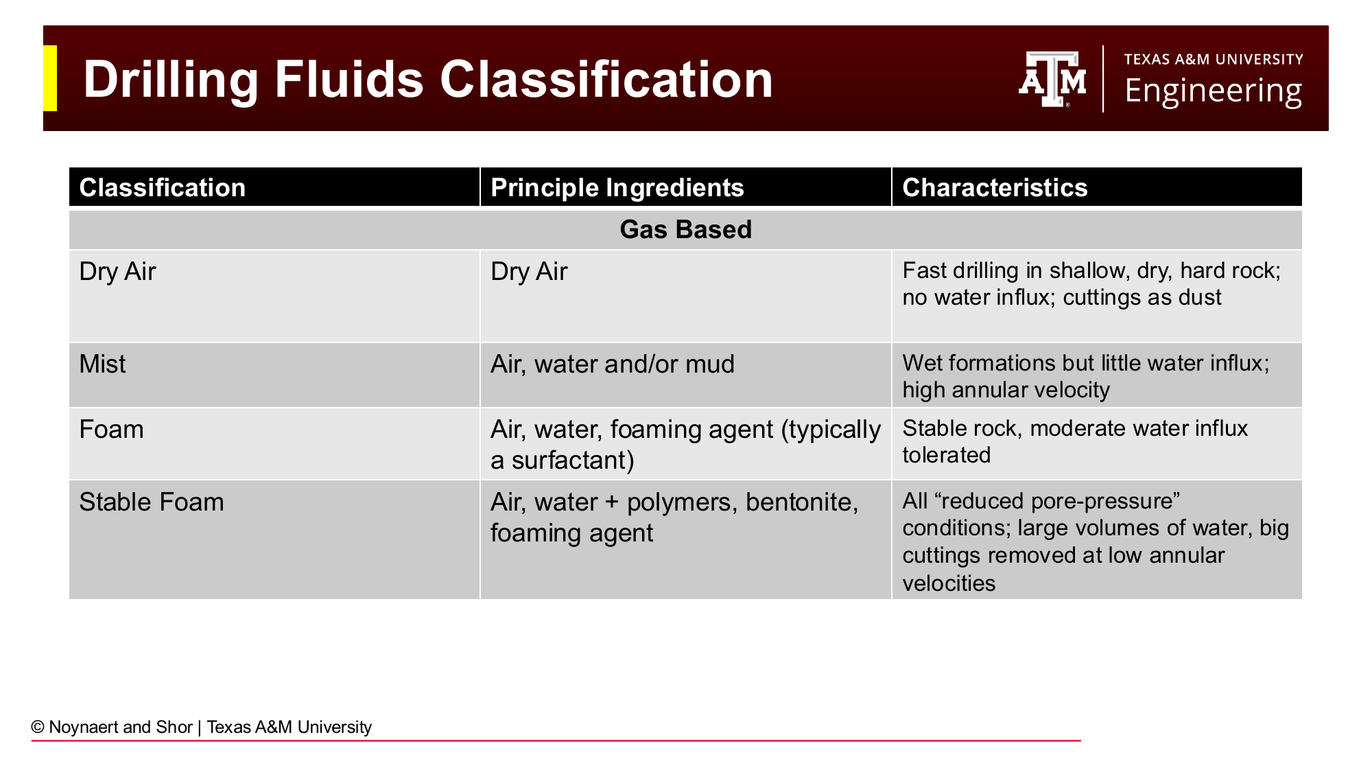
Fig. 38 Classification of gas-based drilling fluids, ranging from dry air to stable foam. These systems are used where formation pressures are low and maximum penetration rate is desired.#
Gas-based systems use compressed air, nitrogen, or natural gas as the circulating medium. Because gas is much less dense than liquid, these systems provide very low bottomhole pressure relative to formation pressure, meaning they are used only in formations with very low pore pressure, or deliberately for underbalanced drilling operations.
Dry air — Fastest drilling rates in shallow, dry, hard rock with no water influx. Cuttings return as dust. Cannot be used where combustible gases may be present.
Mist — Air with a small amount of water or mud injected to handle minor water influx. Provides some lubrication.
Foam — Air, water, and a foaming agent (surfactant). Tolerates moderate water influx; lower annular velocities needed for cuttings transport because foam has much higher effective viscosity than air.
Stable foam — Air, water, polymers, bentonite, and foaming agent. Used for underbalanced drilling, geothermal wells, and coal bed methane where reservoir pressure is too low to support a liquid column.
While drilling acquifers or shallow water zones, air drilling is frequently used as a means of reducing the risk of contamination of drinking water.
4.6.2 Water-Based Muds (WBMs)#
Water-based muds use fresh water, seawater, or brine as the continuous phase. They are the most widely used mud type globally, owing to their lower cost, environmental acceptability, and ease of handling. The wide variety of WBM formulations reflects the range of geological challenges they must address.
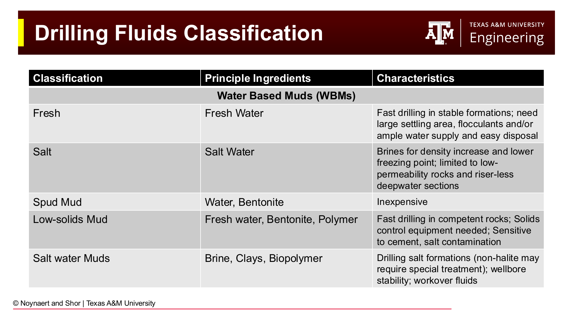
Fig. 39 Common water-based mud formulations, Part 1: fresh water, salt water, spud muds, and low-solids muds.#
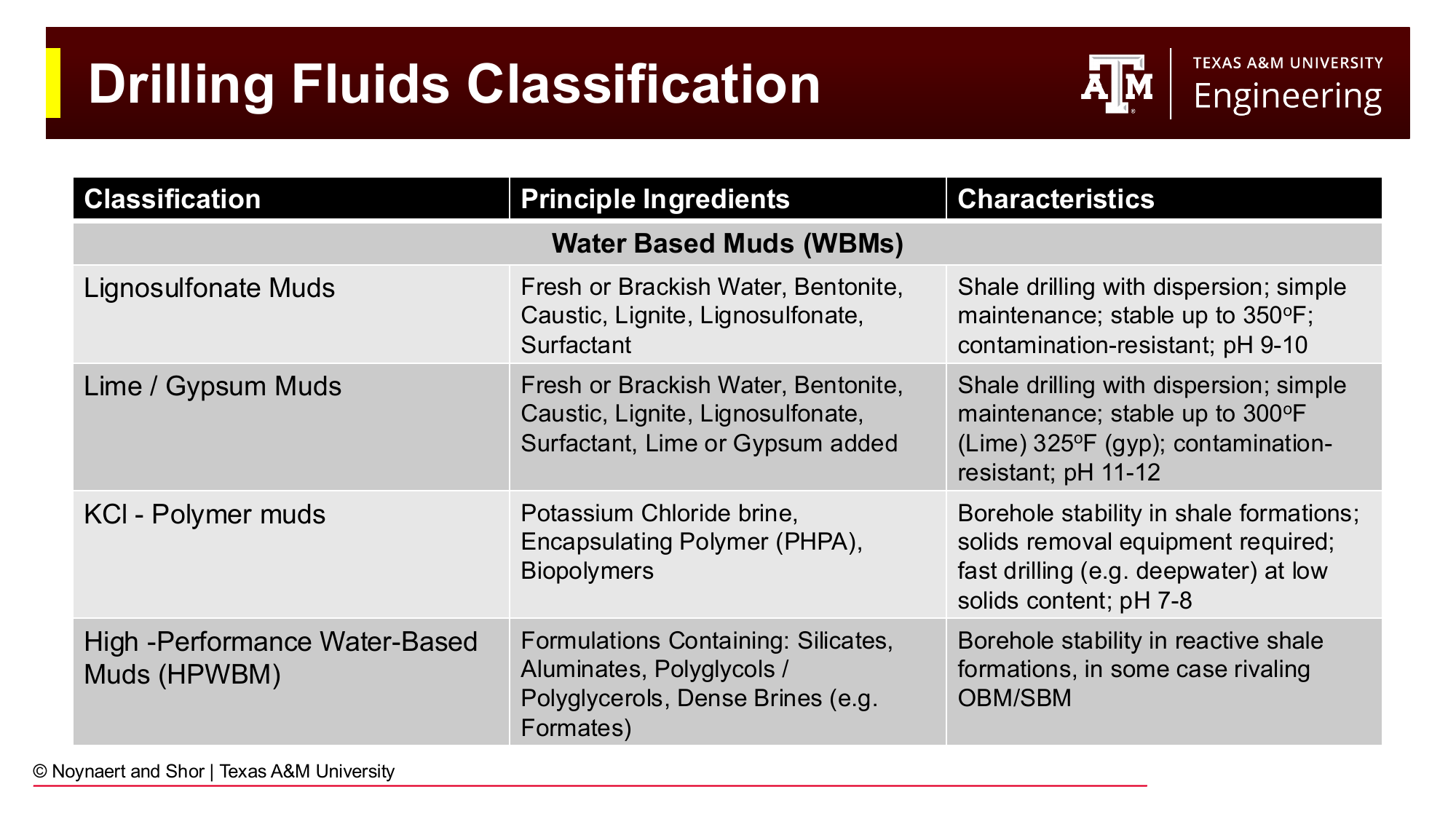
Fig. 40 Common water-based mud formulations, Part 2: lignosulfonate, lime/gypsum, KCl-polymer, and high-performance water-based muds (HPWBMs).#
Key WBM types include:
Spud mud — A simple water/bentonite mixture used for the tophole section. Inexpensive and easy to mix; not suitable for deep or complex wells.
Low-solids mud — Fresh water with minimal bentonite and polymer viscosifiers. Provides fast drilling rates in competent rock but requires active solids control to prevent buildup of drill solids.
KCl-polymer mud — Potassium chloride brine with encapsulating polymers (typically PHPA — partially hydrolyzed polyacrylamide). The K⁺ ions inhibit clay swelling by exchanging with the clay interlayer Na⁺ ions. Widely used for shale drilling, especially in deepwater.
Lignosulfonate mud — Contains lignosulfonate as a thinner/deflocculant. Stable to 175°C (350°F) and resistant to contamination by cement, salt, and calcium. A workhorse system for many land drilling operations.
High-performance WBM (HPWBM) — Modern formulations containing silicates, aluminates, polyglycols, or formate brines, designed to rival OBM performance in shale inhibition while maintaining water-based environmental credentials.
4.6.3 Oil-Based and Synthetic-Based Muds (OBMs/SBMs)#
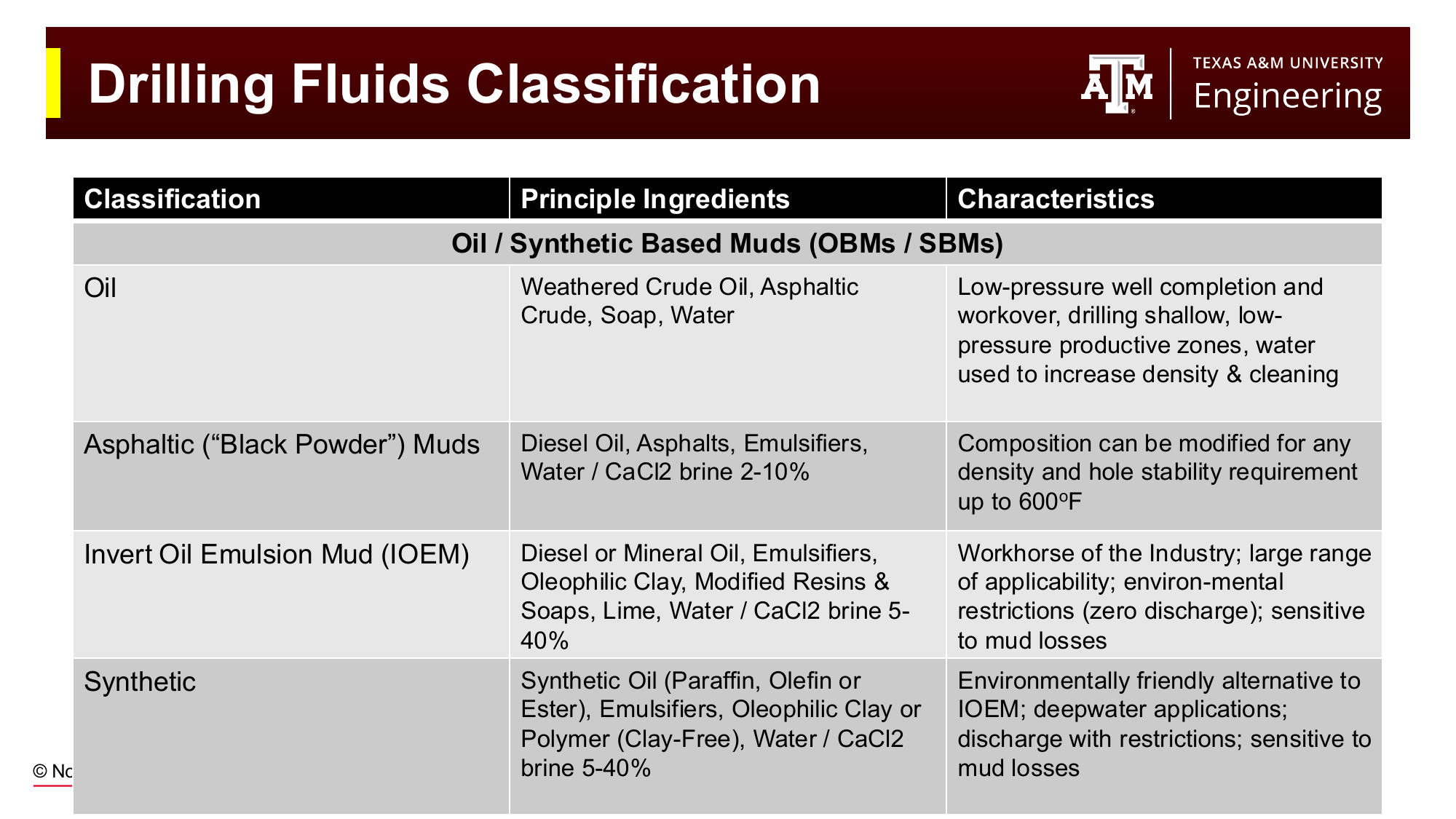
Fig. 41 Classification of oil-based and synthetic-based mud systems. Invert oil emulsion muds are the industry workhorse for difficult shale formations; synthetic-based muds offer similar performance with improved environmental properties.#
In OBMs and SBMs, the continuous phase is oil or a synthetic hydrocarbon, with water dispersed as droplets within the oil (a water-in-oil “invert emulsion”). This configuration gives OBMs/SBMs their key advantage over WBMs: the oil continuous phase does not interact chemically with reactive shale formations, providing superior borehole stability.
Invert oil emulsion mud (IOEM) — The industry workhorse for difficult shales, extended reach wells, and deepwater. Uses diesel or mineral oil as the base, with water/CaCl₂ brine comprising 5–40% of the fluid volume as the dispersed phase. Excellent shale inhibition and thermal stability. The major drawback is environmental restrictions: OBM cuttings cannot be discharged offshore without treatment and are expensive to transport and dispose of onshore.
Synthetic-based mud (SBM) — Replaces diesel or mineral oil with a synthetic hydrocarbon (paraffin, olefin, or ester). Offers similar drilling performance to OBM but with greatly reduced environmental toxicity. SBM cuttings can often be discharged offshore with restrictions. The preferred system for most modern deepwater drilling.
Key Term: Invert Emulsion
An invert emulsion (or water-in-oil emulsion) is a mixture in which small droplets of water are dispersed within a continuous oil phase, stabilized by emulsifying agents. In invert emulsion OBMs and SBMs, the water droplets typically contain dissolved CaCl₂ brine. The oil-continuous nature of the fluid gives it superior shale inhibition compared to water-based muds.
4.7 Mud Composition#
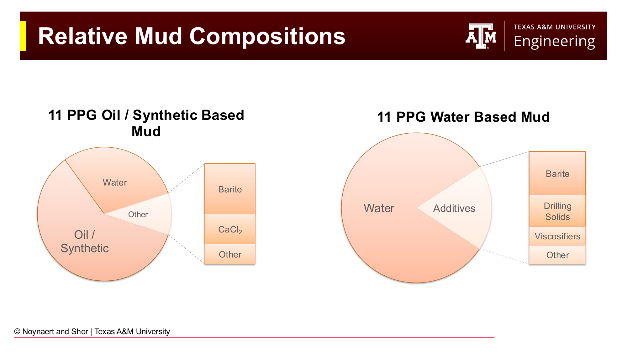
Fig. 42 Comparative composition of an 11 ppg oil/synthetic-based mud (left) and an 11 ppg water-based mud (right). Both systems use barite as the primary weighting agent, but the base fluids and additive packages differ substantially.#
4.7.1 Components of a Water-Based Mud#
The table below summarizes the primary functional components of a water-based mud system:
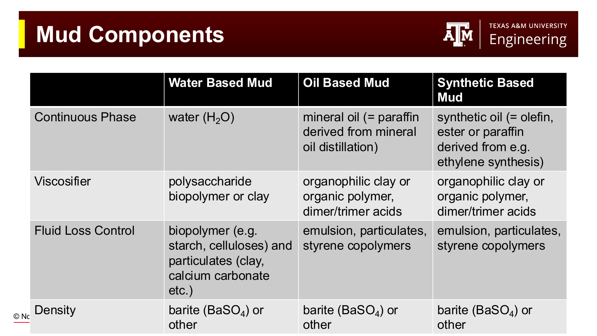
Fig. 43 Key functional components of water-based, oil-based, and synthetic-based mud systems, comparing the materials used to achieve each function across the three base fluid types.#
Continuous phase (water) — Fresh water, seawater, or brine. The continuous phase determines the base chemistry of the system and governs which additives are compatible. When characterizing drilling fluid, it is crtical to utilize the water on site as base fluid chemistry signficantly impact the function of additives.
Viscosifiers — Materials added to increase mud viscosity and provide gel strength:
Bentonite (sodium montmorillonite) — A clay mineral whose platelets carry a surface charge that causes them to form a card-house gel structure at rest. Provides both viscosity and thixotropy (discussed in Chapter 5). The original and still widely used WBM viscosifier.
Biopolymers (xanthan gum, carboxymethylcellulose) — Polysaccharide polymers that provide viscosity at low concentration, with excellent shear-thinning behavior. Xanthan gum (XC polymer) is the standard polymer viscosifier in modern drilling fluids.
Weighting agents — Dense minerals added to increase mud density:
Barite (barium sulfate, BaSO₄) — The standard weighting agent. Specific gravity 4.2; chemically inert and relatively inexpensive. The maximum achievable mud weight with a barite/water system is approximately 22 ppg.
Hematite (iron oxide, Fe₂O₃) — SG 5.1; used when higher densities are needed or when lower solids volume fraction is desired.
Fluid loss control agents — Materials that help form a tight filter cake to minimize filtrate invasion:
Starch, carboxymethylcellulose (CMC) — Biopolymers that plug pores and reduce filtration rate
Sized calcium carbonate — Bridging particles that mechanically seal pore throats; acid-soluble, so they can be removed from the reservoir during completion
Chemical additives — A broad category including pH control agents (caustic soda, lime), lubricants, corrosion inhibitors, anti-foaming agents, biocides (to prevent bacterial degradation of polymers), and shale inhibitors.
4.7.2 Components of OBM/SBM Systems#
The functional roles are the same as in WBMs, but the materials differ because the continuous phase is non-aqueous:
Emulsifiers — Essential in OBM/SBM to stabilize the water-in-oil emulsion. Organic compounds such as polyamines, polyamido-amines, and imidazolines lower the interfacial tension between the oil and water phases, creating a stable emulsion. Water-wet particles (barite, drill cuttings) must be converted to oil-wet by the emulsifier package to avoid disrupting the emulsion.
Organophilic clay — Clay that has been chemically treated to make it oil-dispersible. Provides viscosity in OBM/SBM systems, analogous to bentonite in WBMs.
Lime — Provides alkalinity (controls pH) and acts as an emulsion stabilizer.
CaCl₂ brine (internal phase) — The dissolved CaCl₂ in the dispersed water droplets controls the water activity of the mud. By matching the water activity of the mud to that of the formation water, clay swelling is suppressed — this is the principal mechanism by which OBMs/SBMs inhibit reactive shales.
4.8 Fluid Loss and Filter Cake#
When mud contacts a permeable formation under overbalanced conditions (mud pressure is greater than pore pressure), the differential pressure drives filtrate into the formation. The solid particles in the mud cannot enter the pores and accumulate at the wellbore face, building a filter cake.
Fluid loss is the volume of filtrate that passes through a standard filter paper in a given time under a standard pressure differential. It is a key mud quality indicator:
Too high fluid loss — Excessive filtrate invasion increases pore pressure the near-wellbore rock, can cause clay hydration and borehole enlargement (washout), damages the reservoir by blocking pores, and can cause differential sticking (the drill string becomes stuck against the thick filter cake).
Too low fluid loss — Generally not a problem by itself, but an extremely thick filter cake (from over-treatment with fluid loss additives) can mechanically stick the drill string.
Filter cake quality is as important as the filtration volume:
A thin, tough, low-permeability filter cake is ideal — it forms quickly, limits total invasion, and allows free pipe movement
A thick, soft filter cake is problematic — it reduces the effective borehole diameter and can cause stuck pipe
Fluid loss is measured in the field using an API filtration test: a standard volume of mud is placed in a cell, pressurized to 100 psi across filter paper, and the filtrate volume collected in 30 minutes is recorded in milliliters (mL). High-pressure high-temperature (HPHT) tests are also conducted on muds for hot deep wells.
4.9 Drilling Fluid Requirements#
Beyond performing all their positive functions, drilling fluids must also:
Minimize environmental impact — Cuttings and returned mud must be handled and disposed of in accordance with applicable regulations. OBM/SBM cuttings disposal offshore is strictly regulated; in many jurisdictions, discharge of OBM cuttings to sea is prohibited. The development of SBMs was largely driven by this environmental constraint.
Minimize reservoir damage — Mud invasion that plugs pore throats near the wellbore reduces effective permeability and can permanently impair production. Reservoir sections are typically drilled with carefully designed muds that minimize invasion and use acid-soluble bridging agents. A high skin factor will typically result in an angry call from a reservoir or produciton engineer after the well is handed over to the production team.
Minimize corrosion and equipment wear — Corrosive fluids (low pH, high salinity, dissolved hydrogen sulfide) damage drill pipe, bits, pumps, and wellbore casing. The mud pH is typically maintained alkaline (pH 9–11 for WBMs) to suppress corrosion.
Maximize reusability — Mud is expensive. Systems that can be reconditioned and reused (by removing cuttings and replenishing consumed additives) are preferred over single-use systems.
Be cost-effective — Mud cost is a significant fraction of total well cost. Simpler systems are preferred when the geological environment permits.
4.10 Mud System Selection#
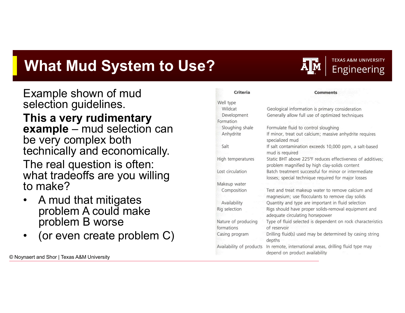
Fig. 44 Example mud selection guidelines. In practice, mud selection involves balancing technical performance, environmental compliance, cost, and the specific challenges of each formation sequence. A mud that solves one problem may worsen another.#
Selecting the appropriate mud system is one of the most important decisions in well planning. No single mud type is optimal for all conditions — every choice involves tradeoffs. Common selection criteria include:
Formation type — Reactive shales and salt formations require strong inhibition; carbonate formations may be drilled with simpler systems
Temperature and pressure — high pressure high temperature (HPHT) wells require thermally stable mud formulations
Environmental regulations — Offshore deepwater operations may prohibit OBM cuttings discharge, favoring SBMs or HPWBMs
Cost — OBMs and SBMs are more expensive than WBMs; the premium must be justified by performance benefits
Compatibility with subsequent operations — The mud must be compatible with the completion fluids and cement systems that follow
A mud that addresses one challenge may create another. For example, a heavily weighted mud provides good pressure control but increases the risk of lost circulation in weaker formations, while a very viscous mud improves cuttings transport but increases swab/surge pressures during tripping. The mud engineer must continuously optimize the fluid system throughout the well.
Worked Examples#
Example 4.1 — Identifying Well Control Risk Factors#
Problem: A drilling crew is pulling the drill string out of the hole at 500 ft/hr to change a worn bit. The formation being drilled is a high-permeability sandstone with a pore pressure of 6,500 psi at 10,000 ft TVD. The current mud weight is 12.5 ppg and the hole is vertical. Identify two potential causes of loss of well control in this scenario and explain what the crew should do to mitigate each.
Solution:
The hydrostatic pressure of the 12.5 ppg mud at 10,000 ft:
The mud pressure exactly equals pore pressure — the well is balanced, not overbalanced. This leaves no margin for any pressure reduction.
Risk 1: Swabbing. Pulling the drill string out of the hole creates a negative surge (swab) pressure in the annulus below the bit. At the current zero overbalance, even a small swab pressure drop will put the wellbore underbalanced, drawing formation fluid in.
Mitigation: Pull the pipe slowly (reduce tripping speed), monitor pit volumes continuously for any gain (indicating fluid influx), and consider increasing mud weight slightly before tripping to provide a positive overbalance margin.
Risk 2: Hole not kept full. As drill collars and pipe are removed from the hole, the volume of steel leaving must be replaced by mud flowing in. If the hole is not monitored and kept full, the fluid level and hydrostatic head will drop.
Mitigation: Fill the hole with mud after every stand pulled (typically every 90 ft), track the volume of mud added versus the theoretical displacement volume of the pipe being removed, and investigate any discrepancy (too little mud being required to fill the hole may indicate an influx of formation fluid from below).
Example 4.2 — Mud Type Selection#
Problem: A drilling engineer is planning a well in the deepwater Gulf of Mexico at 8,000 ft water depth. The well will penetrate 4,000 ft of reactive Tertiary shale before reaching the target carbonate reservoir. The operator has a strict no-discharge policy for cuttings. Evaluate the two most appropriate mud systems and recommend one, justifying your choice.
Solution:
Option 1: KCl-polymer WBM (High-Performance WBM). Provides shale inhibition via K⁺ ion exchange and polymer encapsulation. Cuttings can be discharged to sea (subject to local regulations). Lower cost than SBM. Limitation: May not provide the same level of shale inhibition as OBM/SBM in highly reactive shale; wellbore stability issues are more likely over a long open-hole section.
Option 2: Synthetic-based mud (SBM). Provides excellent shale inhibition (oil-continuous phase, matching water activity via CaCl₂ internal phase). Superior thermal stability and lubrication for the long drill string in deepwater. Cuttings can be discharged with restrictions or treated onboard (consistent with the no-discharge policy for cuttings without treatment). Higher cost than WBM.
Recommendation: SBM. Given the highly reactive shale section (4,000 ft of potential wellbore instability problems), the deepwater environment (long, heavy drill string requiring excellent lubrication), and the HPHT conditions typical at these depths, the performance advantages of SBM over WBM justify the higher cost. The no-discharge policy is accommodated by using a synthetic (rather than diesel) base fluid and treating cuttings onboard. The additional cost of SBM relative to WBM is modest compared to the cost of a wellbore instability event requiring an expensive fishing or sidetrack operation.
Example 4.3 — Filter Cake and Fluid Loss#
Problem: A mud engineer performs an API fluid loss test on a WBM sample and collects 18 mL of filtrate in 30 minutes. The filter cake thickness is measured at 5/32 inch. Industry guidelines suggest a maximum API fluid loss of 10 mL/30 min and a filter cake of no more than 2/32 inch for this formation type.
(a) Is this mud meeting industry guidelines?
(b) What does a high fluid loss indicate about the likelihood of differential sticking?
(c) What types of additives would you add to bring the fluid loss within specification?
Solution:
(a) No. Both parameters exceed the guideline values:
Fluid loss: 18 mL > 10 mL limit
Filter cake: 5/32” > 2/32” limit
The mud’s solids package is not forming a sufficiently tight, thin filter cake.
(b) A thick filter cake (5/32”) creates a physical pad of soft filter cake between the drill string and the borehole wall. If the drill string is held stationary against the filter cake — for example, during a connection — the differential pressure across the filter cake (mud pressure minus pore pressure) pushes the pipe into the cake and can hold it with tremendous force. This is differential sticking, one of the most expensive stuck pipe scenarios because it is difficult to free and often requires jarring, spotting a releasing pill, or in extreme cases, sidetracking the well. A 5/32” filter cake significantly elevates this risk.
(c) To reduce fluid loss and thin the filter cake:
Add a starch or CMC (carboxymethylcellulose) fluid loss control agent — these biopolymers plug pore throats in the filter cake and reduce filtration rate
Add sized calcium carbonate or other bridging agents — sized particles help seal the filter paper (formation face) quickly, limiting total invasion
Increase the concentration of existing viscosifiers — a higher bentonite or polymer concentration produces a denser, less permeable filter cake
Check and adjust pH — improper pH can reduce the effectiveness of fluid loss additives
Practice Problems#
4.1 For each of the following well scenarios, identify the most likely cause of loss of well control from the list in Section 4.4, and briefly explain your reasoning.
(a) A well is being drilled at 11,000 ft TVD. The mud weight is 10.2 ppg and the pore pressure gradient is 9.8 ppg EMW. The crew has been circulating bottoms-up and notices the pit volume has increased by 5 barrels over the last 30 minutes without any pipe movement or pump rate change.
(b) A crew is tripping out of the hole at 800 ft/hr. They are filling the hole every five stands (approx. every 450 ft). The mud engineer notices that the hole is taking less mud than the calculated displacement volume of the pipe being pulled.
(c) A well is being drilled near an area where a producing field has been under water injection for 15 years. While drilling a shallow sand at 1,500 ft, the well takes a kick despite the mud weight being appropriate for the normal pore pressure gradient in the area.
Solution
(a) Rapidly drilling a hydrocarbon-bearing sand, or insufficient fluid density in a localized zone. The pit gain without pipe movement or pump changes is a classic kick indicator. Gas dissolved in formation fluid may have reduced the effective mud density in the annulus as it migrated upward (“gas-cut mud”), further reducing hydrostatic pressure and allowing more influx.
(b) Hole not kept full — but in the reverse sense. Taking less mud than expected means some fluid is already occupying the space where mud should be going — the annulus is partially filled with formation fluid (a kick). The discrepancy between the expected fill volume and the actual fill volume is a critical early kick indicator during tripping. The crew should immediately stop tripping and perform a flow check (shut the pumps off and watch whether the well flows).
(c) Charged / pressurized formation. The 15 years of water injection in the adjacent field has pressurized formations in the area. The shallow sand at 1,500 ft, which would normally be at low pore pressure, has been charged to a higher-than-normal pressure by the injected water migrating through connected sands. The standard mud weight for this area’s normal pore pressure is insufficient for the pressurized sand.
4.2 A 12.0 ppg WBM is composed of water, bentonite, and barite. The mud engineer needs to increase the density to 13.5 ppg by adding more barite. Using your knowledge of mud composition:
(a) Will the volume of the mud system increase, decrease, or stay approximately the same when barite is added? Explain.
(b) What effect would adding barite alone (without adjusting other components) likely have on the viscosity of the mud?
(c) If the increased viscosity is undesirable, what general approach would the mud engineer take to correct it?
Solution
(a) Increase. Adding barite adds both mass and volume to the system. The total volume of mud increases as the barite solids are mixed in, unless an equivalent volume of base fluid is removed. In practice, mud volume management is important on a rig because the mud tanks have finite capacity.
(b) Viscosity will tend to increase. Adding more solids to any mud increases its apparent viscosity. This is both a direct effect (more particles = more resistance to flow) and potentially an indirect effect (increased solids can increase gel strength).
(c) The mud engineer would add a thinner or deflocculant — chemicals such as lignosulfonate, lignite, or a dispersant that reduce the tendency of clay particles to form a gel structure by reducing electrostatic attraction between clay platelets. Alternatively, if the viscosity increase is unacceptable and thinners alone are insufficient, the mud system can be diluted with water (which reduces density, partially offsetting the barite addition) or partially replaced with a lower-viscosity base.
4.3 Match each drilling fluid type to the scenario where it would be most appropriate. Use each type once.
Fluid types: (1) Dry air, (2) Stable foam, (3) Spud mud, (4) KCl-polymer WBM, (5) Invert oil emulsion (OBM), (6) Synthetic-based mud (SBM)
Scenarios: (a) Drilling a 200-ft conductor hole through unconsolidated surface soils; no pressure concerns; simplicity is the priority.
(b) Drilling through a highly reactive Tertiary shale formation on an onshore well in Texas; environmental regulations are not restrictive; wellbore stability is the primary concern.
(c) Drilling a geothermal well in Nevada through volcanic rock at low formation pressure; the objective is maximum penetration rate.
(d) Drilling a deepwater Gulf of Mexico well through 6,000 ft of reactive shale; no-discharge policy is in place; HPHT conditions expected.
(e) Drilling through a shale formation in a deepwater well where borehole stability is critical and environmental performance is nearly as important as drilling performance.
(f) Drilling a shallow exploratory well in Wyoming through competent sandstones at low pressure; the primary concern is borehole stability in reactive shale interbeds.
Solution
(a) → (3) Spud mud — Simple, inexpensive, suitable for shallow unconsolidated sections
(b) → (5) Invert oil emulsion (OBM) — Best shale inhibition; no offshore discharge restrictions on onshore Texas well; performance justifies cost for difficult reactive shale
(c) → (1) Dry air — Volcanic rock in Nevada is typically hard, competent, and at low pressure; air drilling delivers the highest penetration rate and zero fluid cost
(d) → (6) Synthetic-based mud (SBM) — No-discharge policy rules out diesel OBM; SBM provides OBM-level performance with environmentally acceptable cuttings; handles HPHT conditions
(e) → (6) Synthetic-based mud (SBM) — Also SBM; same reasoning as (d) but here the question emphasizes the balance between performance and environmental credentials
(Note: for a two-SBM answer, the intent is that (d) and (e) both correctly map to SBM. In practice, HPWBM might be used for (f) and SBM reserved for (d/e).)
(f) → (4) KCl-polymer WBM — Cost-effective inhibitive WBM for a relatively shallow well with interbedded reactive shale; K⁺ inhibition and polymer encapsulation provide adequate shale stability at lower cost than OBM/SBM
4.4 Explain, in engineering terms, why a drilling fluid with strong thixotropic (gel-forming) properties is desirable during pipe connections and undesirable during the initial pump startup after a connection. What design parameter is used to quantify gel strength, and how is it measured?
Solution
Why thixotropy is desirable during a connection: When drilling stops for a pipe connection, the mud pumps are shut off and circulation ceases. If the mud were purely viscous (non-thixotropic), gravity would cause cuttings loaded in the annulus to settle rapidly toward the bottom of the hole. A thixotropic mud builds a gel structure within seconds to minutes of being at rest, suspending cuttings in place so that when circulation resumes, the hole is clean rather than full of settled cuttings. This prevents cuttings from packing around the drill string (pack-off) and potentially causing stuck pipe.
Why thixotropy is undesirable at pump startup: When the pumps restart after a connection, the gelled mud must be broken before it will flow again. Breaking a strong gel requires a spike in pump pressure. If the gel strength is too high (a “progressive” gel that gets stronger with time), the pressure required to initiate flow may exceed the fracture gradient of weak formations, causing lost circulation. This is known as a “gel breaking surge.”
Ideal behavior: The gel should be “flat” — it should build quickly to a moderate strength and then not continue to strengthen significantly over time (the 10-second gel, 10-minute gel, and 30-minute gel strengths should be approximately equal). A progressive gel (where 30-minute gel >> 10-second gel) is a warning sign.
Measurement: Gel strength is measured with a Fann VG (or Fann 35) viscometer by stopping the rotation, waiting a specified rest period (10 seconds, 10 minutes, or 30 minutes), and then restarting rotation at 3 rpm. The maximum dial deflection at the instant of gel breaking is recorded as the gel strength in lb/100 ft².
4.5 A well is being drilled offshore with an OBM. The mud engineer is monitoring a gradual decrease in mud density over three consecutive mud checks (from 14.2 to 14.0 to 13.8 ppg) even though no additional water or base oil has been added to the system. The rig is drilling through a porous limestone at the time.
(a) What is the most likely explanation for this observation?
(b) What is the potential consequence if this trend continues?
(c) What would you do to diagnose and correct the problem?
Solution
(a) The most likely explanation is gas influx or gas dissolution from the porous limestone. Gas from the formation is entering the mud and reducing its effective density (gas “cutting” the mud). Even small amounts of dissolved or entrained gas can significantly reduce mud density because gas has very low density. Another possibility is brine influx (formation water flowing into the mud), which, if lower density than the OBM, would also reduce density, though this is less dramatic.
(b) If the density continues to decrease, the hydrostatic pressure at the bottom of the hole will fall below formation pore pressure, and the well will be underbalanced. The gas influx rate will increase, further cutting the mud and further reducing hydrostatic pressure — a positive feedback loop that can quickly escalate from a minor influx to a full kick and potentially a blowout.
(c) Diagnosis and correction:
Increase monitoring frequency — take more frequent mud weight readings and watch for pit volume increases
Check for gas returns — use the gas detectors on the mud returns to quantify the level of gas in the returning mud
Perform a flow check — shut the pumps off and observe whether the well continues to flow (indicating a kick) or stops (no influx)
If a kick is confirmed — follow well control procedures: shut-in the well using the BOPs, circulate out the gas using the choke manifold (wait and weight or driller’s method)
Weight up the mud — once the influx is controlled, increase the mud density by adding barite to restore overbalance and prevent recurrence
Consider a trip to check the BHA — if gas influx is continuous, a bit check or BHA inspection may be needed after the well is secured
Summary#
This chapter has introduced drilling fluids — arguably the most critical and complex system in a drilling operation:
Drilling fluids (muds) serve multiple simultaneous functions: providing primary well control through hydrostatic pressure, transporting cuttings to surface, stabilizing the borehole, lubricating and cooling the bit and drill string, forming a protective filter cake on permeable formations, and supporting downhole information transmission.
Loss of primary well control (a kick) can result from insufficient mud density, lost circulation, swabbing, surging, the hole not being kept full, charged formations, high penetration rates in gas sands, or gas hydrate dissociation. The mud is the first and most important barrier; mechanical barriers (BOPs, casing) are secondary.
Drilling fluids are classified by base fluid: gas-based (air, mist, foam), water-based (WBMs), oil-based (OBMs), and synthetic-based (SBMs). Each class has characteristic advantages, limitations, and appropriate applications.
All mud systems share the same functional components (continuous phase, viscosifier, weighting agent, fluid loss control agent, and chemical additives) but achieve these through different materials depending on the base fluid.
Fluid loss control is critical for reservoir protection and prevention of differential sticking. The ideal filter cake is thin, tough, and low-permeability.
Mud selection involves balancing technical performance, environmental regulations, cost, and compatibility with well construction objectives. There is no universal best mud type — every well requires its own evaluation.
Chapter 5 covers how the key properties of drilling fluids — density, viscosity, rheology, fluid loss, and chemical composition — are measured and interpreted in the field. Chapter 6 covers the calculations used to design and modify mud systems.
References#
Mitchell, R.F. and Miska, S.Z. (eds.), Fundamentals of Drilling Engineering, Society of Petroleum Engineers, 2011.
Al-Majed, A.A., Hossain, M.E., and Al-Majed, A., Fundamentals of Sustainable Drilling Engineering, John Wiley and Sons, 2015.
API RP 13B-1, Recommended Practice for Field Testing Water-based Drilling Fluids, American Petroleum Institute.
API RP 13B-2, Recommended Practice for Field Testing of Oil-based Drilling Fluids, American Petroleum Institute.