Chapter 11 — Introduction to Directional Drilling#
Learning Objectives#
By the end of this chapter, students should be able to:
Explain why wells are drilled directionally and identify the major field applications of directional drilling.
Define the key wellbore geometry terms: measured depth, true vertical depth, inclination, azimuth, horizontal departure, and dogleg severity.
Describe the three standard 2D well profile shapes — build and hold, S-type, and continuous build — and identify which situations each is suited for.
Explain what a wellbore survey is and how it is used to determine wellbore position.
Describe the operating principles of passive, semi-active (mud motor), and active (rotary steerable) directional drilling systems.
Distinguish between push-the-bit and point-the-bit rotary steerable architectures.
11.1 Why Drill Directionally?#
For most of the early history of oil and gas drilling, the goal was to keep the wellbore as close to vertical as possible. A vertical well is the simplest path from surface to reservoir: it requires no special equipment, minimizes the length of drill string required, and makes casing and cementing straightforward. The problem is that many of the world’s oil and gas reservoirs cannot be accessed efficiently — or at all — from directly above.
Directional drilling is the practice of intentionally steering a wellbore along a prescribed three-dimensional path. What began as a tool for avoiding collisions and bypassing obstructions has become central to how the industry accesses resources. The vast majority of wells drilled today deviate from vertical, and many are horizontal for a significant portion of their length.
Key Term
Directional drilling is the practice of intentionally controlling the trajectory of a wellbore to reach a subsurface target that is not located directly beneath the surface location.
11.1.1 Applications#
The reasons to drill directionally fall into several broad categories.
Sidetracks. A sidetrack is an operation in which the original wellbore is plugged at some depth and a new path is initiated off the existing hole. Sidetracks are used when a well has missed its geological target, when equipment has been lost in the hole and cannot be retrieved, or when the original well encounters an unfavorable geologic hazard. The top portion of the original hole is reused, saving the cost of drilling from surface.
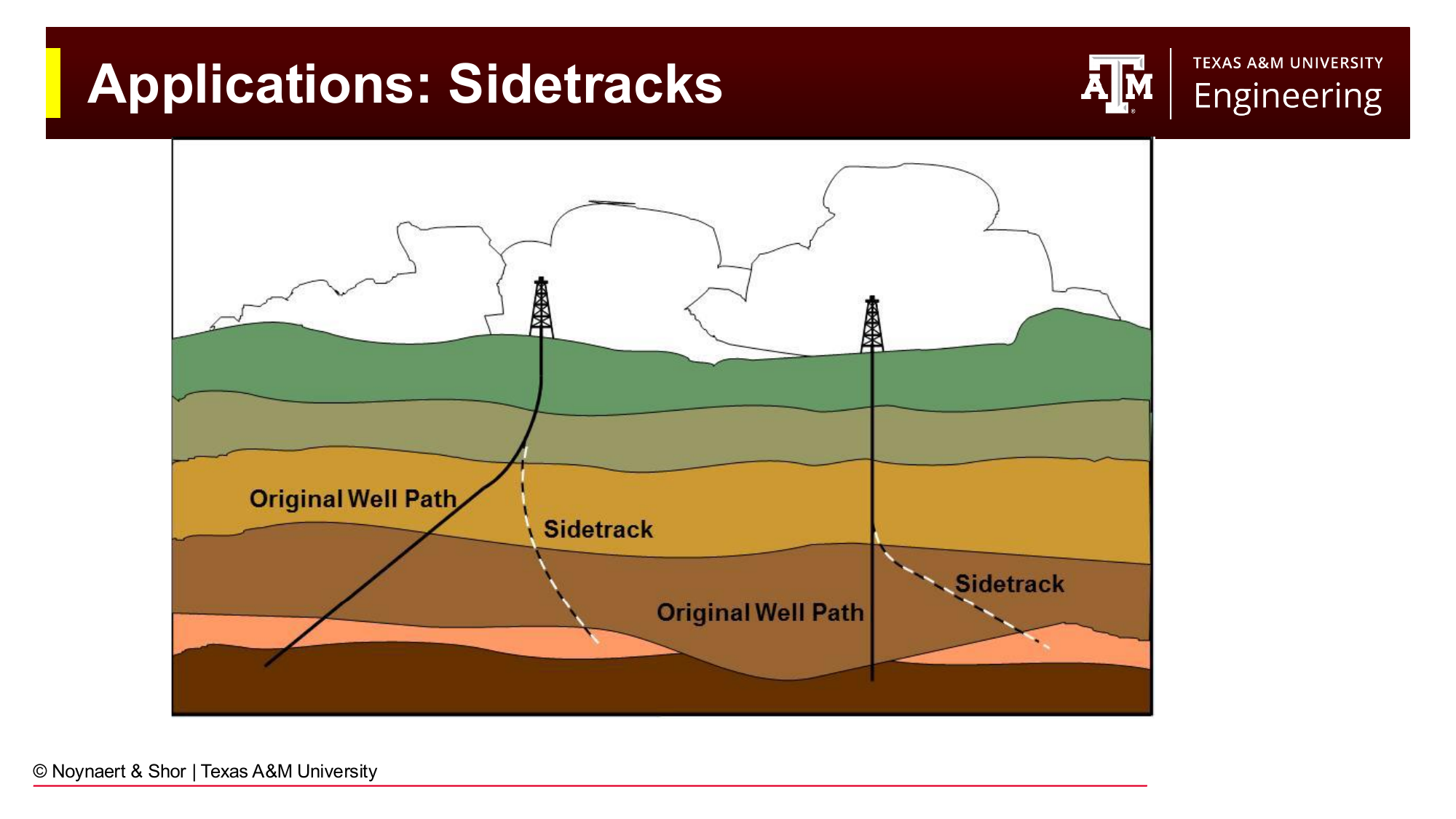
Fig. 139 Sidetrack operations plug the original wellbore and deviate onto a new path, reusing the upper portion of the hole.#
Well path corrections. Even a well planned as vertical will wander from the desired trajectory due to geology, bit design, and BHA behavior. Directional drilling tools allow the engineer to correct the path and stay within the prescribed target box.
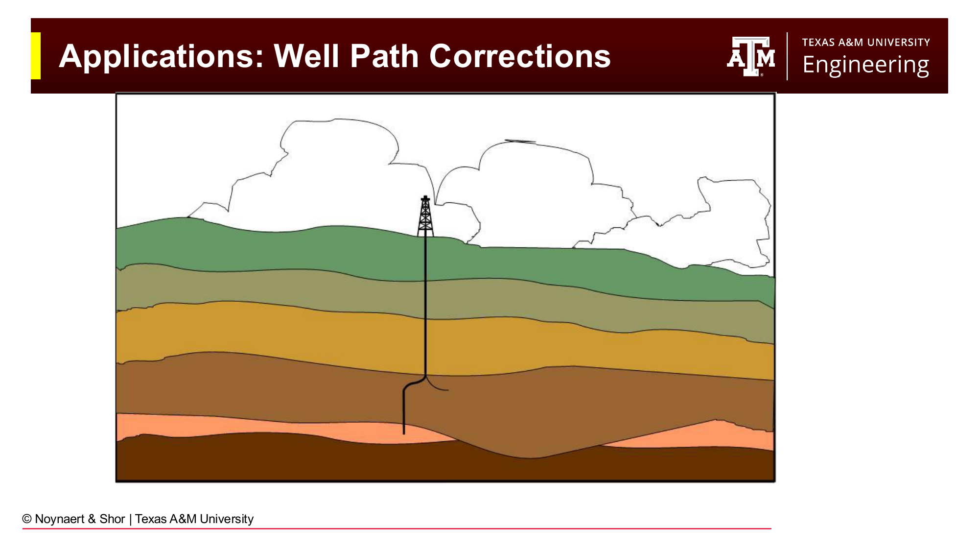
Fig. 140 Directional tools are used to correct unintended deviations from the planned well path.#
Shoreline and inaccessible field development. When the surface location for a rig is separated from the subsurface target by coastlines, populated areas, or terrain that makes rig placement impractical, directional drilling allows access from a more suitable location. The Sakhalin-I project off the coast of Russia is a well-known example: icebergs make offshore drilling dangerous for much of the year, so wells are drilled from the shore and steered far out under the seafloor to reach the offshore reservoir. At the time of their completion, these extended-reach wells held world records for horizontal departure.
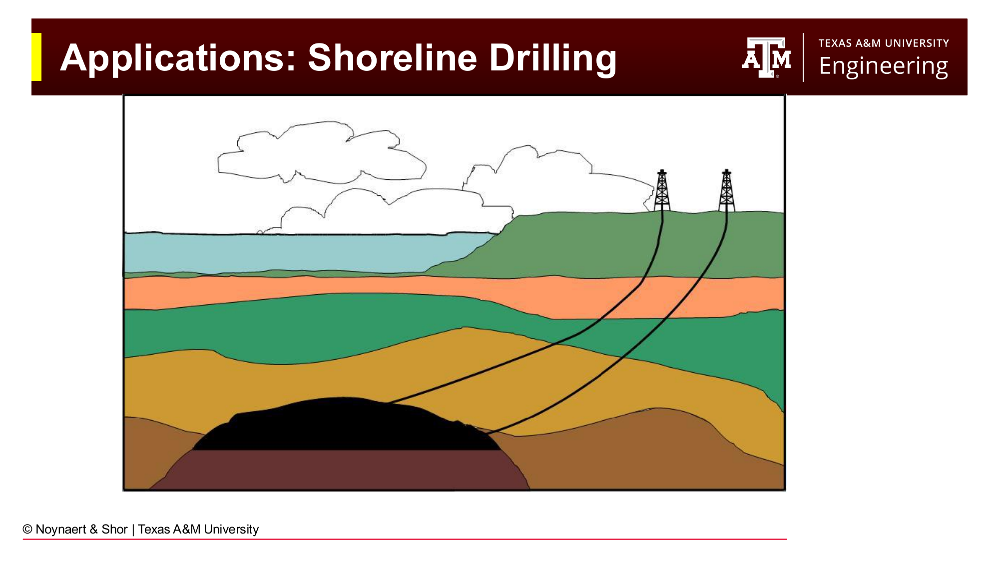
Fig. 141 Shoreline drilling places the rig on land and drills extended-reach wells beneath the ocean, avoiding harsh offshore conditions.#
Offshore platform development. A fixed or floating offshore platform represents a very large capital investment that is not easily relocated. Rather than requiring one platform per well, modern development drilling places many wells from a single platform. Directional drilling allows the platform to access a broad area of the reservoir from one surface location. The wells radiate outward from the platform like the spokes of a wheel, each reaching a different part of the field.
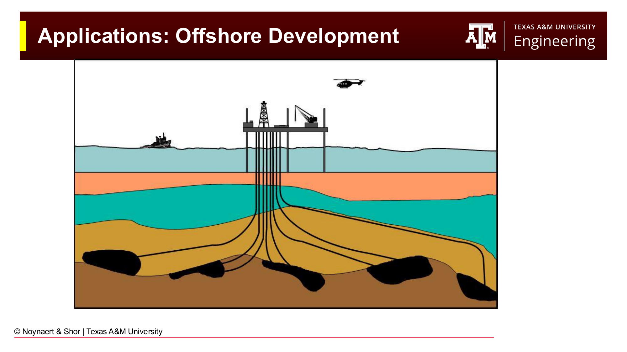
Fig. 142 Offshore platforms use directional drilling to access many reservoir targets from a single fixed location.#
Salt dome avoidance. Salt domes are bodies of mobile, plastic salt that have been squeezed upward through overlying sediments. Oil and gas can accumulate on the flanks of a salt dome where the rising salt has deformed the surrounding rocks. Drilling through salt is extremely difficult: the salt creeps into the borehole, it dissolves in water-based drilling fluid, and it imposes severe collapse loads on casing. Directional drilling allows the well to approach the reservoir target from an angle that skirts around the salt body entirely.
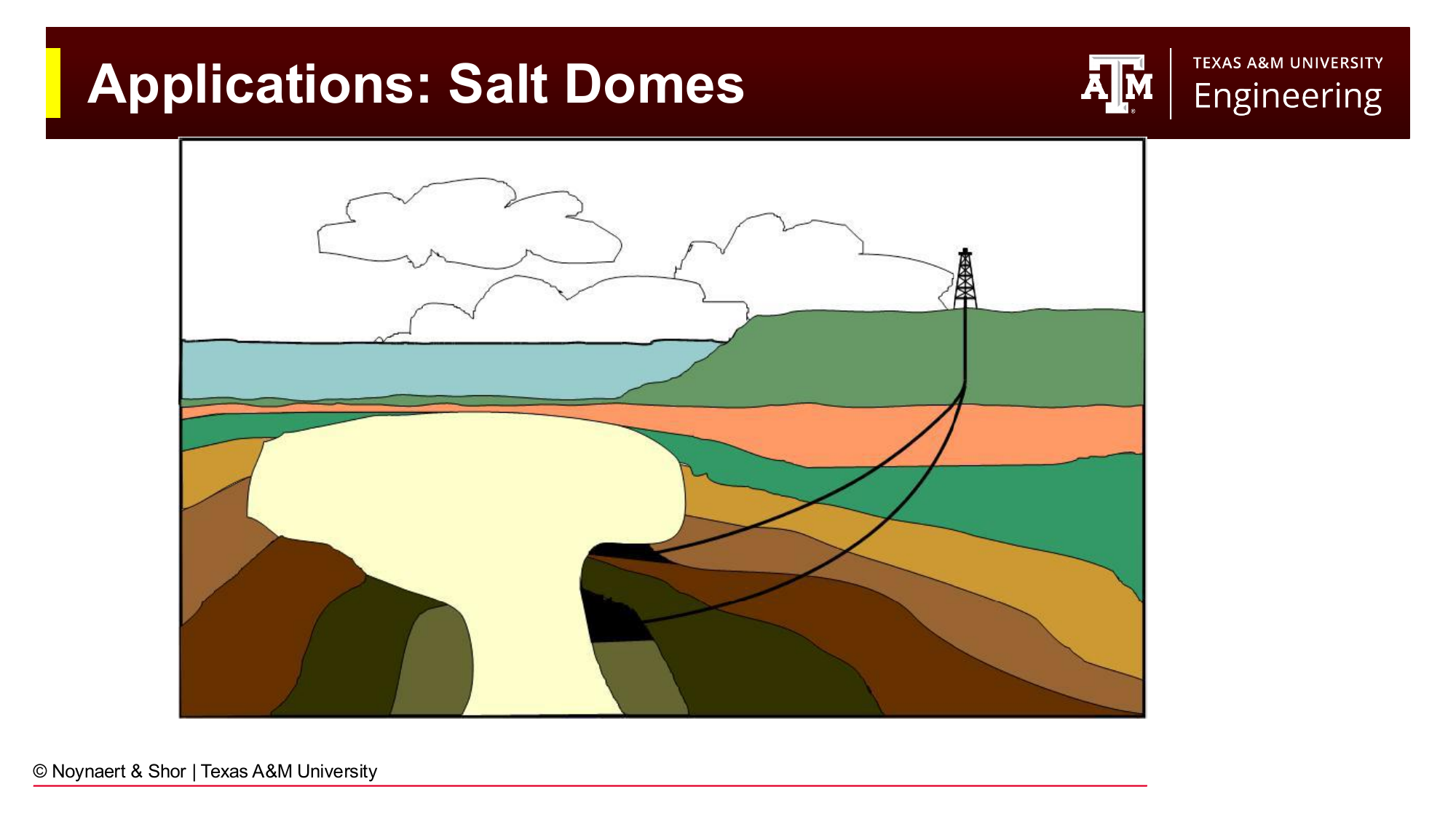
Fig. 143 Salt dome reservoirs are accessed by directional wells that avoid drilling through the mobile, creeping salt body.#
Urban and environmentally sensitive areas. The Los Angeles Basin is among the most productive petroleum provinces in the history of the United States and also one of the most densely urbanized. Drilling rigs in downtown Los Angeles are concealed inside purpose-built structures designed to look like ordinary commercial buildings. Wells from these sites are directionally drilled to reach reservoirs beneath the city without visible surface disturbance. Similar approaches are used near wildlife refuges, offshore protected zones, and other environmentally sensitive areas.
Re-entry and multilateral wells. A multilateral well is one in which multiple wellbores branch off a common parent well. The parent may be vertical or deviated, and the individual laterals may go in different directions to access different parts of a reservoir, different reservoir intervals, or even different fields. Directional techniques are required both to drill the laterals and to re-enter them if workover operations are required later.
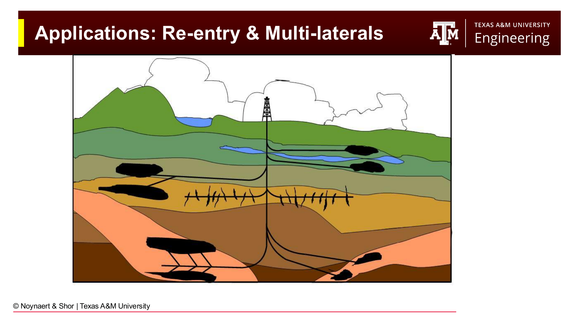
Fig. 144 Multilateral wells branch from a parent wellbore to access multiple reservoir targets from a single surface location.#
Relief wells. When a well blows out and the original wellhead is destroyed or inaccessible, the only remaining option may be to drill one or more relief wells from a safe standoff distance. The relief well is steered to intersect the blowing well at depth, after which heavy drilling fluid is pumped through the intersection to kill the blowout from below. The Deepwater Horizon blowout of 2010 required two relief wells to be drilled in the deepwater Gulf of Mexico to intersect and kill the Macondo well.
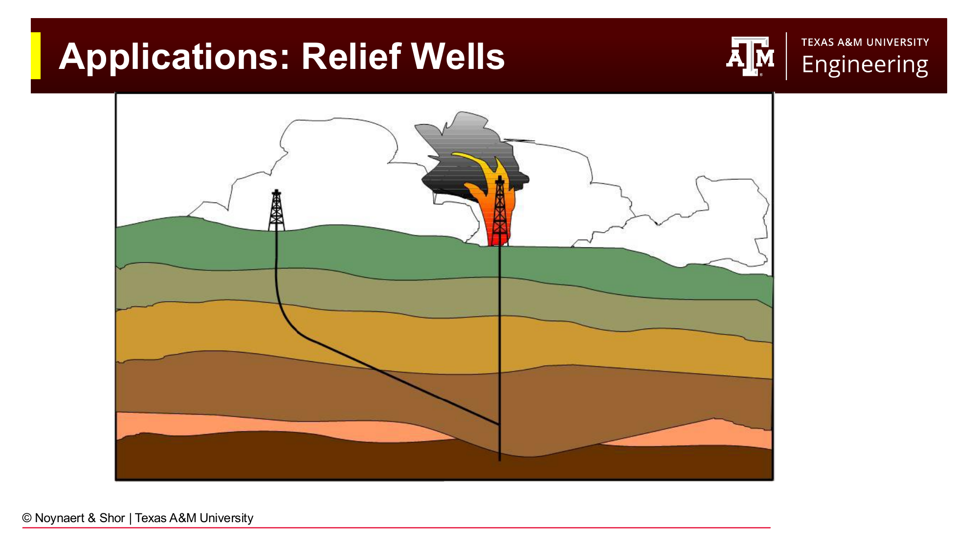
Fig. 145 Relief wells are directionally drilled to intersect a blowing well at depth, allowing it to be killed with heavy mud.#
11.2 Wellbore Geometry: Definitions#
To describe, plan, and navigate a directional well, engineers need a precise vocabulary for wellbore geometry. These terms appear constantly in survey reports, well plots, and directional drilling programs.
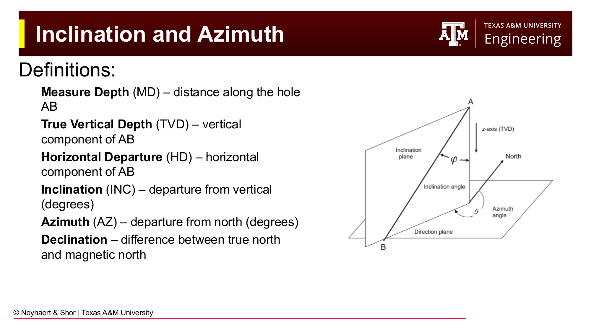
Fig. 146 The primary geometric quantities used to describe a wellbore trajectory.#
11.2.1 Depth Measurements#
Measured depth (MD) is the physical length of the wellbore from the reference point at surface to the point of interest. It is measured along the path of the wellbore itself — not straight down. The reference point is usually the rotary kelly bushing (RKB) on the rig floor, which sits some distance above ground level or mean sea level.
True vertical depth (TVD) is the vertical component of the wellbore path — the straight-down distance from the surface reference to the point of interest. For a perfectly vertical well, MD and TVD are identical. For any deviated well, TVD is less than MD.
Key Term
Measured depth (MD) is the length along the wellbore path. True vertical depth (TVD) is the vertical component of the wellbore position. The difference MD − TVD grows as well inclination increases.
11.2.2 Direction Measurements#
Inclination (also written INC) is the angle of the wellbore measured from vertical at any given point. A perfectly vertical wellbore has an inclination of 0°. A perfectly horizontal wellbore has an inclination of 90°. Inclination is always a positive number between 0° and 180° (though values above 90° indicate an upward-pointing section and are unusual in practice).
Azimuth (also written AZ) is the compass direction the wellbore is pointing at any given point, measured clockwise from true north. A well pointing due north has an azimuth of 0°; east is 90°; south is 180°; west is 270°. A perfectly vertical wellbore has no azimuth — it is not pointing in any horizontal direction — so azimuth is undefined or irrelevant at inclinations near zero.
Declination is the angular difference between true (geographic) north and magnetic north at a given surface location. Because downhole survey tools use magnetometers to determine direction, and the magnetic north pole does not coincide with the geographic north pole, a correction must be applied to convert magnetic azimuth readings to true azimuth. The magnetic north pole has moved significantly over the past century — from northern Canada toward Siberia — so declination corrections must be updated regularly and are location-dependent. Models for global magnetic field declination are now updated every five years.
Key Term
Inclination is the angle of the wellbore from vertical (0° = vertical, 90° = horizontal). Azimuth is the compass direction of the wellbore, measured clockwise from true north. Declination is the correction applied to convert magnetic north readings to true north.
11.2.3 Positional Quantities#
Horizontal departure (HD) is the horizontal distance from the surface location to the point of interest, measured as a straight-line distance in map view. It does not account for the direction of that departure — it is a scalar distance, not a vector.
Northing and easting are the vector components of the horizontal position. Northing is the north-south component (positive toward true north) and easting is the east-west component (positive toward east). These correspond to the y- and x-axes of a map coordinate system centered on the wellhead. Together, they give the full 2D position of any point along the wellbore in map view.
Departure is the horizontal distance between any two points in the wellbore (not necessarily surface and the point of interest).
Closure is the straight-line horizontal distance from the wellhead to the final target point.
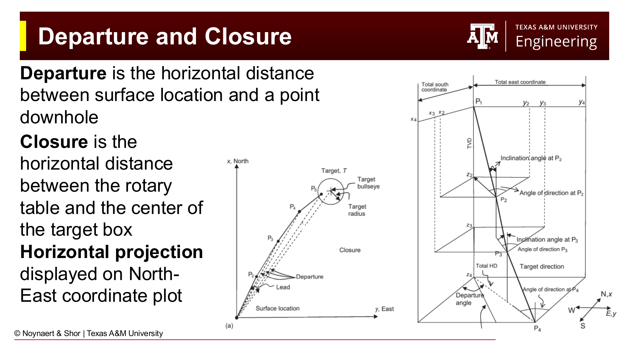
Fig. 147 Departure measures horizontal distance between any two points; closure measures from wellhead to target.#
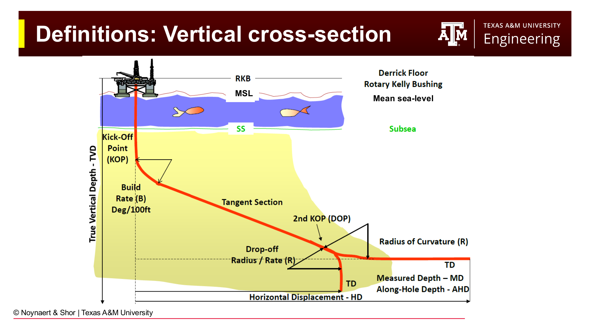
Fig. 148 Vertical cross-section view showing measured depth, true vertical depth, and horizontal departure. The Kelly bushing (KB) elevation above mean sea level (MSL) provides the reference datum.#
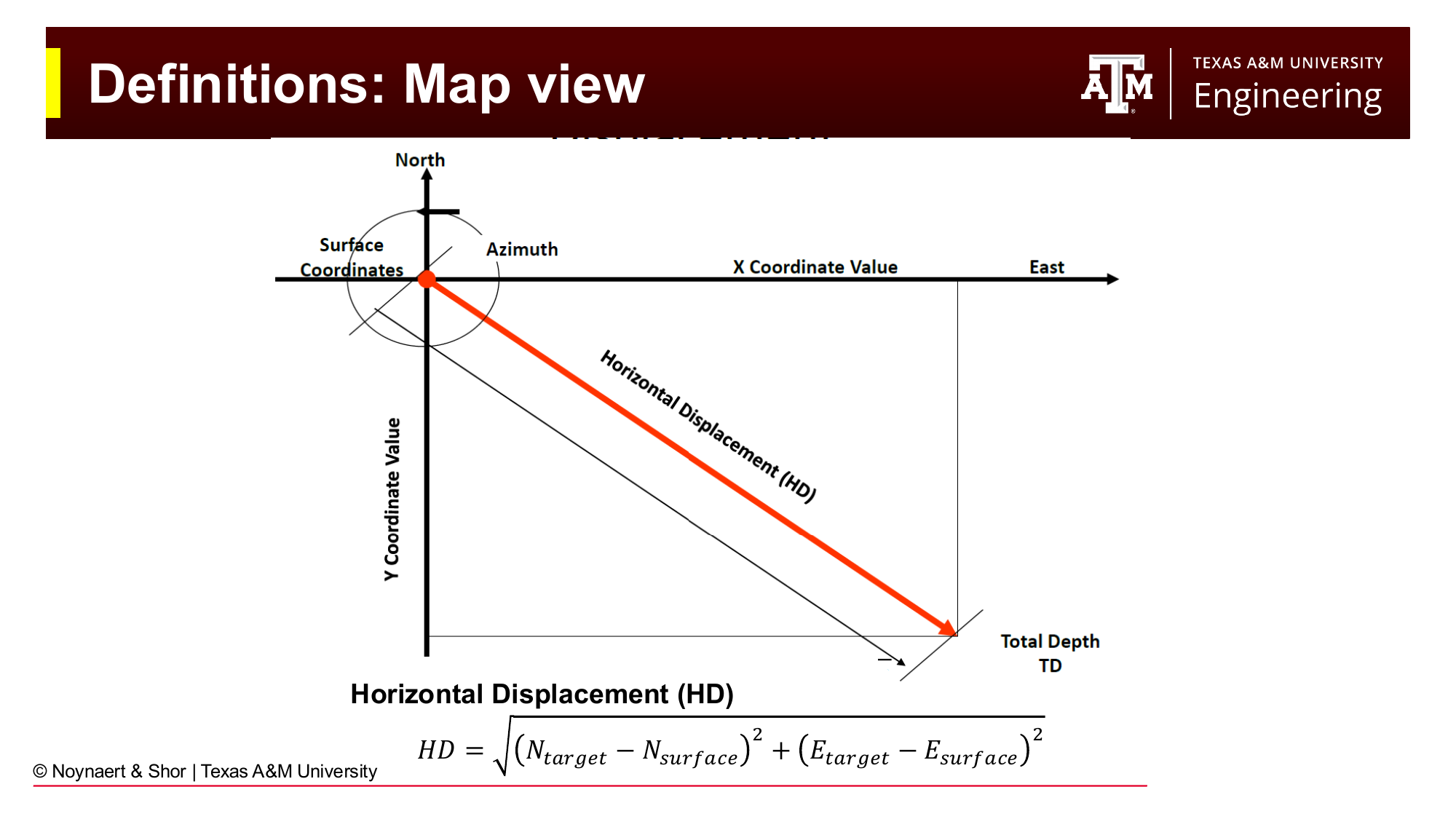
Fig. 149 Map view of a directional well showing northing and easting coordinates. Horizontal displacement (HD) is the straight-line distance from wellhead to the point of interest.#
11.3 The Wellbore Survey#
A wellbore survey is the set of measurements that describe where the wellbore actually is underground. It consists of a table of measured depth, inclination, and azimuth readings taken at regular intervals as the well is drilled:
MD (ft) |
INC (°) |
AZ (°) |
|---|---|---|
0 |
0 |
0 |
… |
… |
… |
Survey measurements are typically taken every 20 to 100 feet along the wellbore. From this table of three measured quantities, the engineer calculates TVD, northing, easting, and horizontal departure at each survey station. Together these computed quantities give the three-dimensional position of the wellbore.
Modern wells almost universally use measurement while drilling (MWD) tools to obtain surveys in real time as the well is being drilled. An MWD package is placed in the BHA just behind the drill bit and contains accelerometers (to measure inclination) and magnetometers (to measure azimuth). Data are transmitted to surface through pressure pulses in the drilling fluid, allowing the driller and directional driller to monitor and control the wellbore path continuously.
Older and simpler surveys were run on wireline by lowering sensors into the drilled wellbore after the fact. These methods are still used for verification or in wells where real-time MWD is not justified by cost.
Key Term
A wellbore survey is a table of MD, inclination, and azimuth measurements at regular depth stations. From these three measured quantities, TVD, northing, easting, and horizontal departure are calculated to determine the 3D wellbore position.
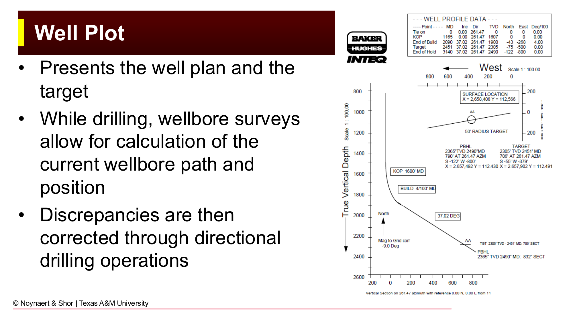
Fig. 150 A well plot presents the planned well path and the actual surveyed position. Discrepancies between planned and actual positions are corrected by adjusting the directional drilling program.#
11.4 Dogleg Severity and the Well Plan#
11.4.1 Dogleg Angle and Dogleg Severity#
A well that is turning — changing inclination or azimuth — traces a curved path. That curve can be described geometrically as an arc of a circle with radius \(R\). Three related terms describe the curvature:
Dogleg angle (\(\beta\)): the total angular change over a curved section, in degrees. If the well builds from 0° inclination to 45° inclination, the dogleg angle is 45°.
Dogleg severity (DLS): the rate of angular change, expressed in degrees per 100 feet (or degrees per 30 m in SI). DLS is the same quantity as build-up rate (BUR) when inclination is increasing, or drop-off rate (DOR) when inclination is decreasing.
Radius of curvature (\(R\)): the radius of the circular arc described by the curved section.
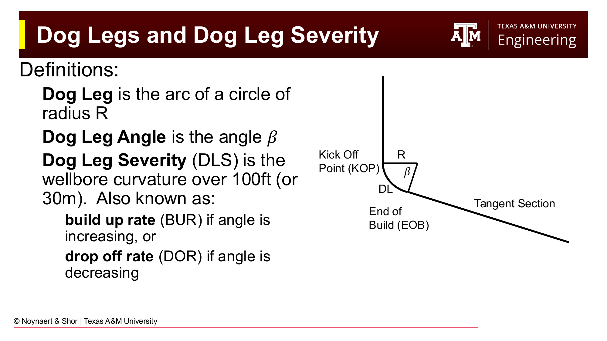
Fig. 151 The dogleg angle \(\beta\) is the total angular change in a curved section. Dogleg severity (DLS) is the rate of that change per 100 feet. The curved section traces a circular arc of radius \(R\).#
The radius of curvature and DLS are inversely related:
A DLS of 5°/100 ft corresponds to a radius of curvature of about 1,146 feet — a very gentle curve. A DLS of 30°/100 ft corresponds to a radius of only 191 feet — a much tighter bend that would be difficult to run casing through.
Key Term
Dogleg severity (DLS) is the rate of wellbore curvature, expressed in degrees per 100 feet. It is related to radius of curvature \(R\) by:
Typical DLS values range from 3°/100 ft (gentle, long-radius) to 15°/100 ft (moderate) to 30°/100 ft (tight).
11.4.2 Standard Well Profile Types#
Almost all directional wells can be described by one of three 2D profile shapes:
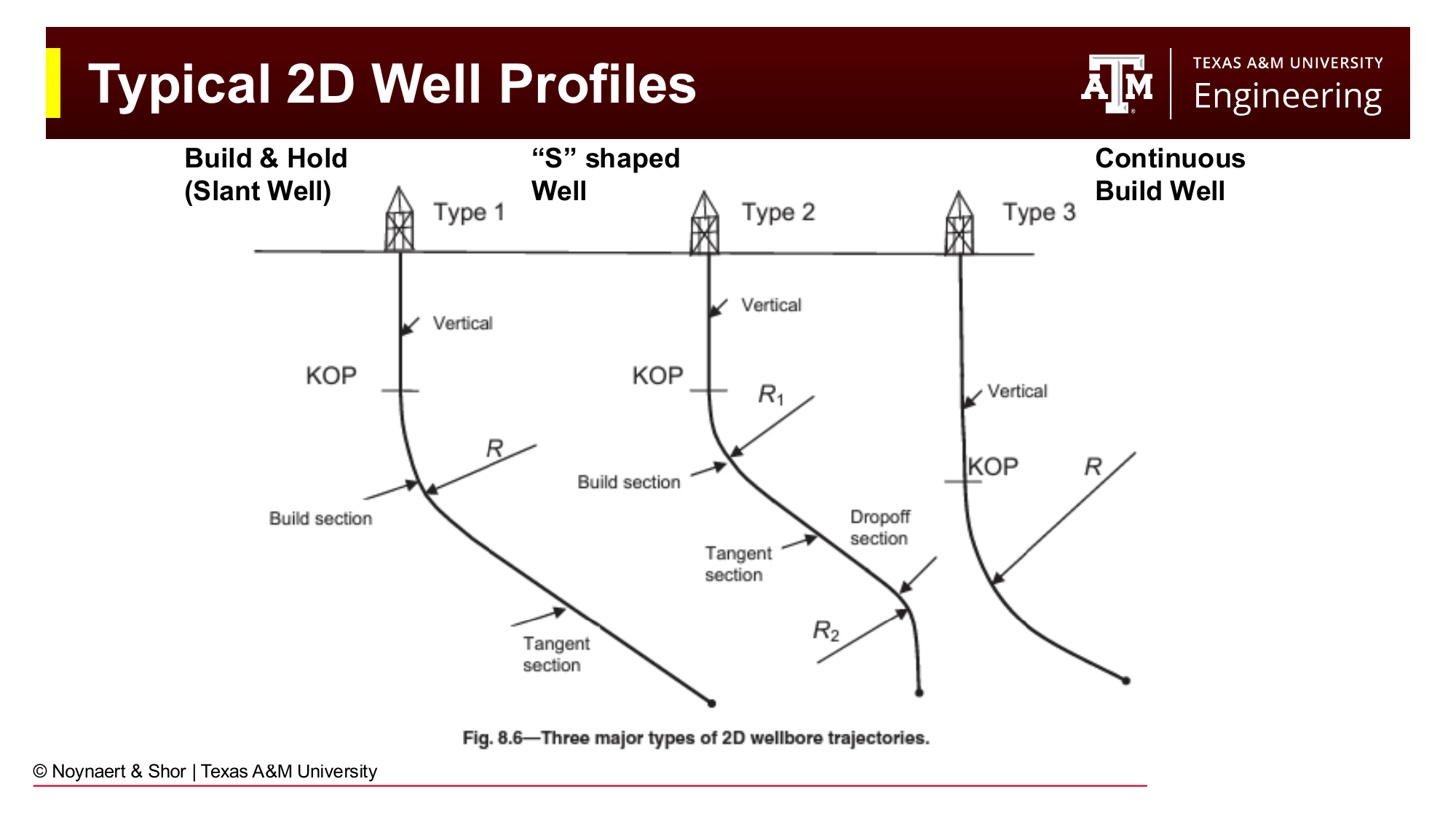
Fig. 152 The three standard 2D well profiles: build-and-hold (left), S-type (center), and continuous build (right).#
Build and hold. The well drills vertically to a kickoff point (KOP), then builds inclination at a constant DLS to a target angle, then holds (tangent section) at that angle for the remainder of the well. This is the most common profile for horizontal wells, deviated production wells, and extended-reach wells. When the tangent angle is 80–100°, the well is a horizontal well.
S-type (or S-shaped) well. The well drills vertically to a first KOP, builds to some intermediate angle, holds that tangent angle for a distance, then drops back toward vertical. The result is a well that has moved its surface-to-reservoir horizontal departure but arrives at the reservoir target in a mostly vertical orientation. S-type wells are used when reservoir access must be vertical (e.g., for gravity drainage) but the target cannot be reached from directly above.
Continuous build. The well builds from surface continuously, without a tangent hold section. This is less common but is used in certain tight-radius applications.
Key Term
The kickoff point (KOP) is the depth at which the wellbore first deviates from vertical. Below the KOP, the build section increases inclination at the design DLS. The tangent section holds a constant inclination and azimuth until the target or the next KOP.
11.4.3 The Extended-Reach Envelope#
There is a practical limit to how far a well can depart horizontally from its surface location. Drill string weight, friction, torque, and material strength all impose constraints. A commonly referenced plot of well depth versus horizontal departure (the Reach-vs-Depth diagram) shows that shallower wells can achieve far greater horizontal departures relative to their depth, while deep wells tend to be more nearly vertical. The Sakhalin extended-reach wells drilled from shore to offshore targets hold world records for total horizontal departure at roughly 40,000 feet.
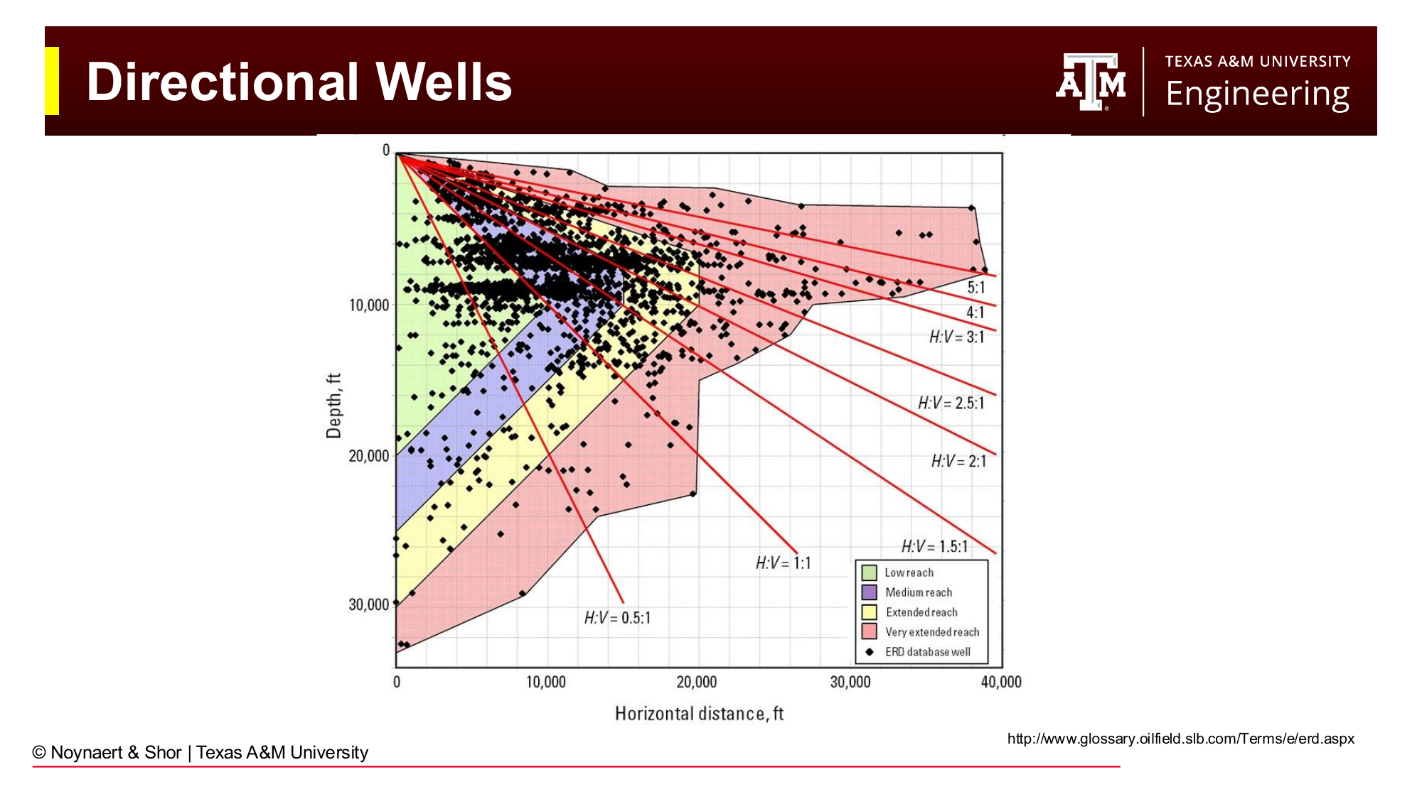
Fig. 153 Extended-reach well depth versus horizontal departure envelope. Shallower wells can achieve greater relative departures; ultra-deep wells are limited by drill string mechanics.#
11.5 Geologic Hazard Planning: The Zechstein Example#
One of the most important applications of directional well planning is navigating around geologic hazards. The Zechstein formation — a thick evaporite (salt) sequence found across much of northwestern Europe — provides a classic illustration of how well path design must respond to geology.
Consider a reservoir target located beneath a Zechstein salt dome. Four different trajectory strategies can be evaluated:
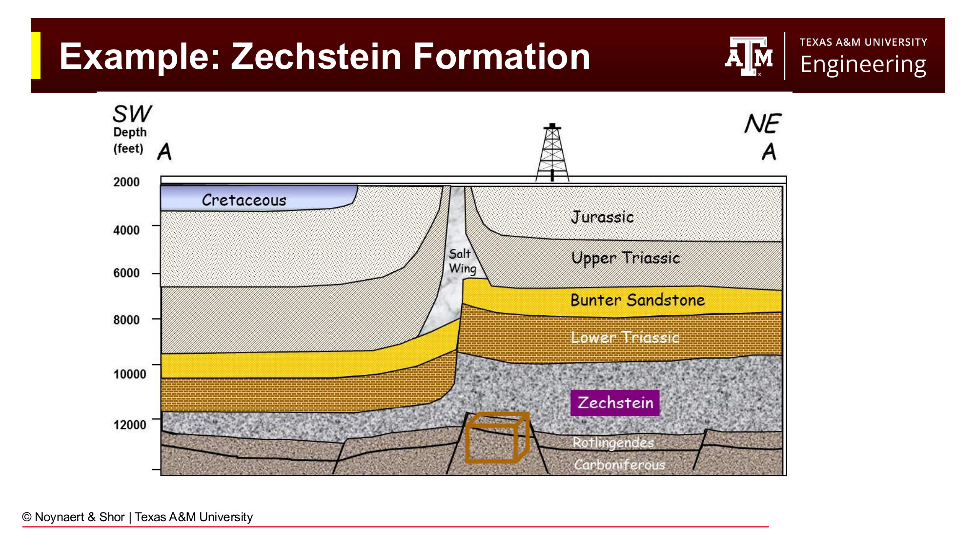
Fig. 154 The Zechstein salt dome presents a major geologic hazard. The reservoir target is accessible from several trajectory approaches, each with different trade-offs.#
A vertical well drilled directly above the target would penetrate the salt dome — an engineering nightmare of creeping salt, dissolution, and extreme casing loads.
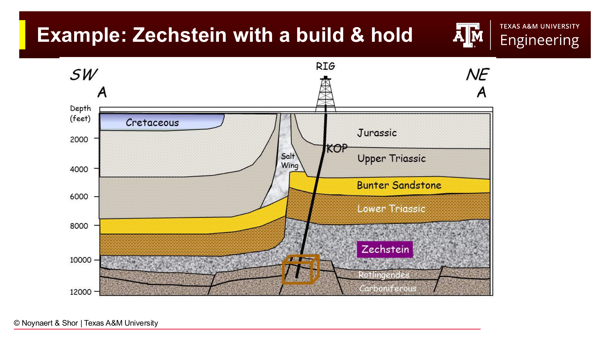
Fig. 155 A build-and-hold well drills around the edge of the salt body and lands in the reservoir at an angle.#
A build-and-hold well can be designed to build angle early and skirt the flank of the salt. This avoids the worst of the salt, though the trajectory may still graze the salt edge.
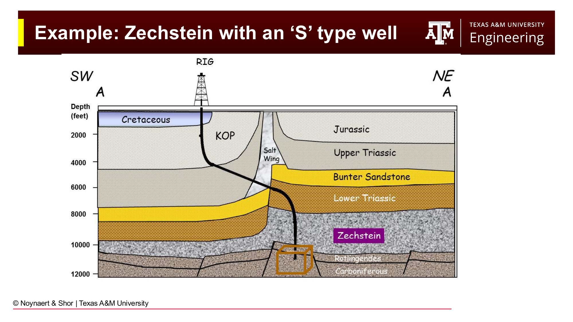
Fig. 156 An S-type well builds angle, moves laterally past the salt, then drops back toward vertical to enter the reservoir.#
An S-type well can build angle, clear the salt body, then drop back toward vertical to penetrate the reservoir in a more nearly vertical orientation — which may be preferred for completion or production reasons.
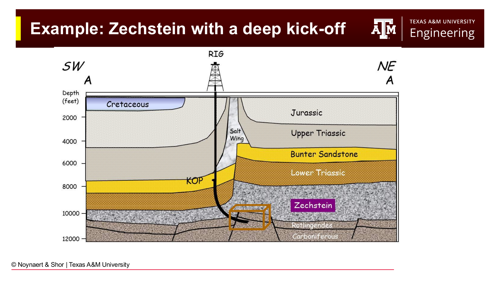
Fig. 157 A deep kickoff point keeps the well vertical until below the salt, then builds to reach the flanking reservoir.#
A deep kickoff places the KOP below the base of the salt, drilling vertically through the salt (acceptable if the salt is thin enough and manageable) and then kicking off at depth to reach the flanking reservoir.
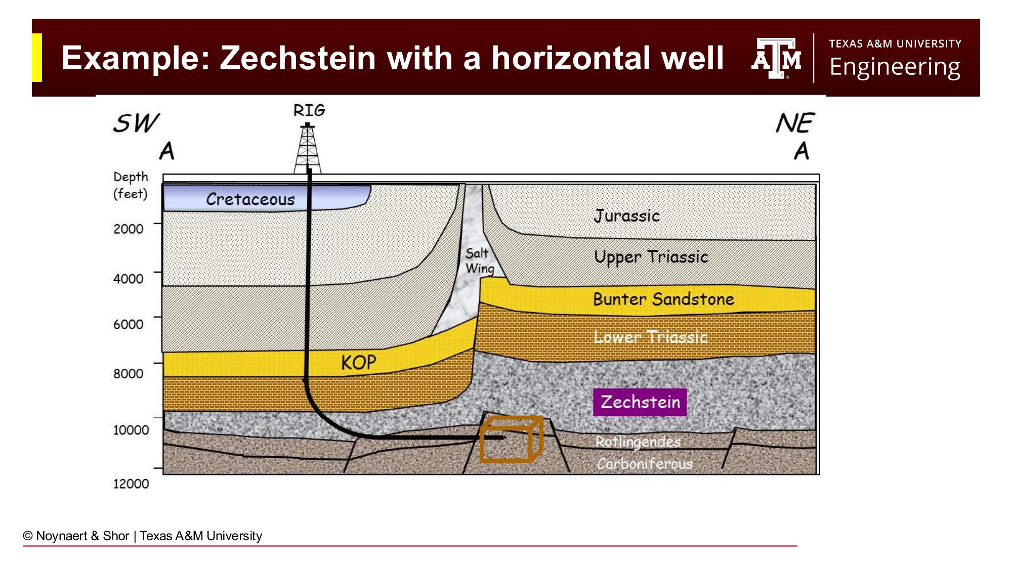
Fig. 158 A horizontal well approaches the reservoir from the side, maximizing contact with the reservoir while completely avoiding the salt dome.#
A horizontal well can be designed to approach the flanking reservoir entirely from the side, landing horizontally and maximizing reservoir contact while staying well clear of the salt.
The choice among these options depends on reservoir geometry, completion strategy, drilling fluid compatibility with the evaporite, and the cost of the resulting well length.
11.6 Directional Drilling Systems#
Once the well path is planned, the engineer selects the tools and techniques that will be used to execute it. Directional drilling systems fall into three broad categories: passive, semi-active, and active.
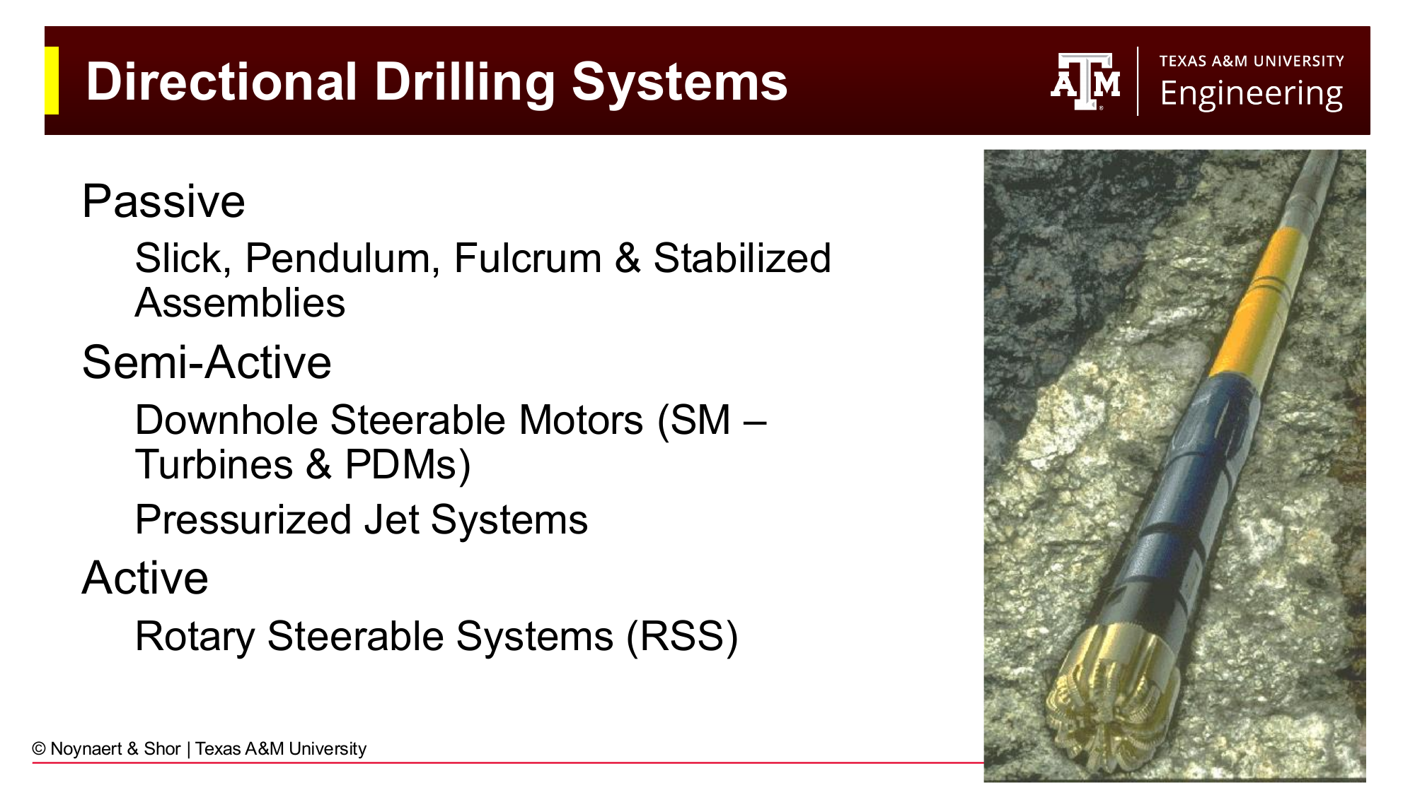
Fig. 159 Directional drilling systems classified by their degree of active control.#
11.6.1 Passive Systems#
Passive directional systems are BHA configurations whose directional tendency arises from the geometry of the components — not from any actively controlled mechanism downhole or at surface.
Whipstocks are wedge-shaped tools that are set in the casing or open hole at a prescribed depth and orientation. The drill bit and BHA are forced off the wedge face and thereby deflected in a specific direction. Whipstocks were the original directional drilling tool and are still used to initiate sidetracks.
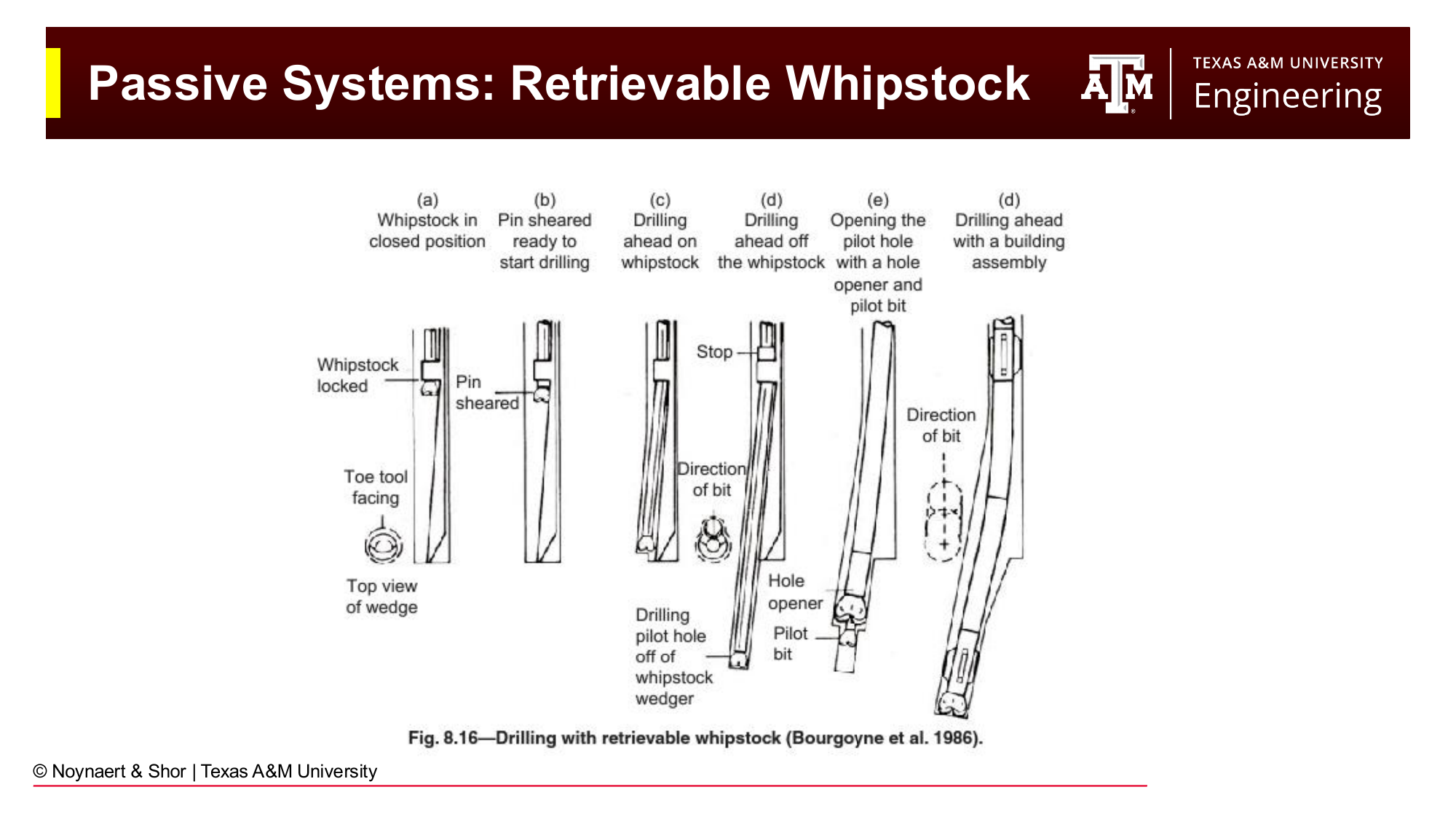
Fig. 160 A retrievable whipstock is set at the kickoff point and recovered after the new wellbore has been initiated.#
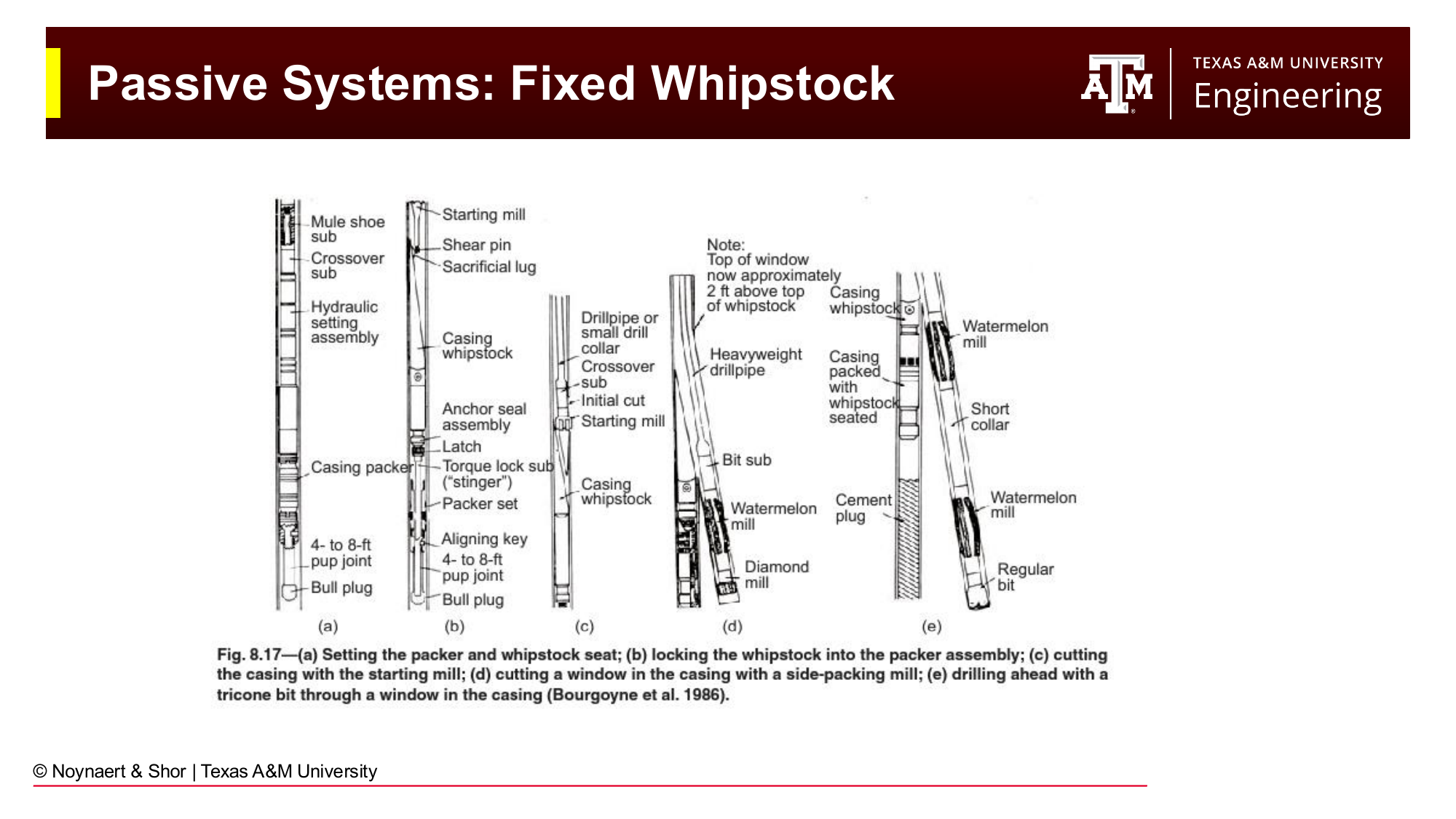
Fig. 161 A fixed (permanent) whipstock is cemented in place and remains in the wellbore.#
Jetting uses an asymmetric flow from one large nozzle on the drill bit to erode rock preferentially in one direction, steering the bit without rotating the drill string. Jetting is limited to very soft formations and is rarely used today.
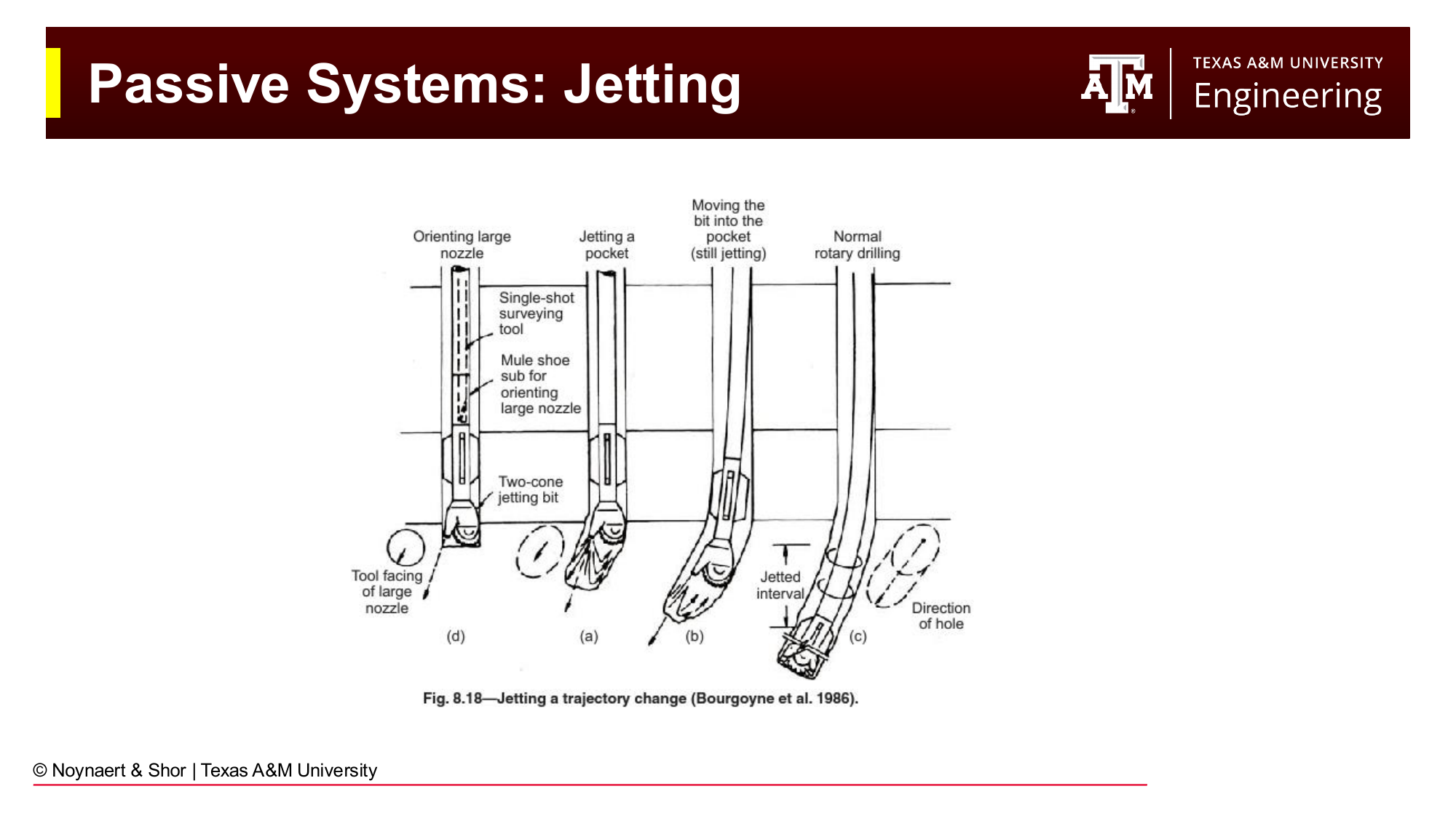
Fig. 162 Jetting uses asymmetric fluid flow from a single large nozzle to erode rock in a preferred direction, steering the bit in soft formations.#
Slick BHAs (BHAs with no stabilizers) and stabilizer-based assemblies exploit the natural tendency of the BHA to sag under its own weight in an inclined borehole. The position of stabilizers in the BHA determines whether the bit tends to build angle (fulcrum assembly) or drop angle (pendulum assembly):
Pendulum (dropping) assembly: A stabilizer is placed some distance behind the bit, with no near-bit stabilizer. Gravity causes the bit to drop — reducing inclination.
Fulcrum (building) assembly: A stabilizer is placed very close to the bit. The BHA above the near-bit stabilizer sags away from the high side of the hole, levering the bit upward — increasing inclination.
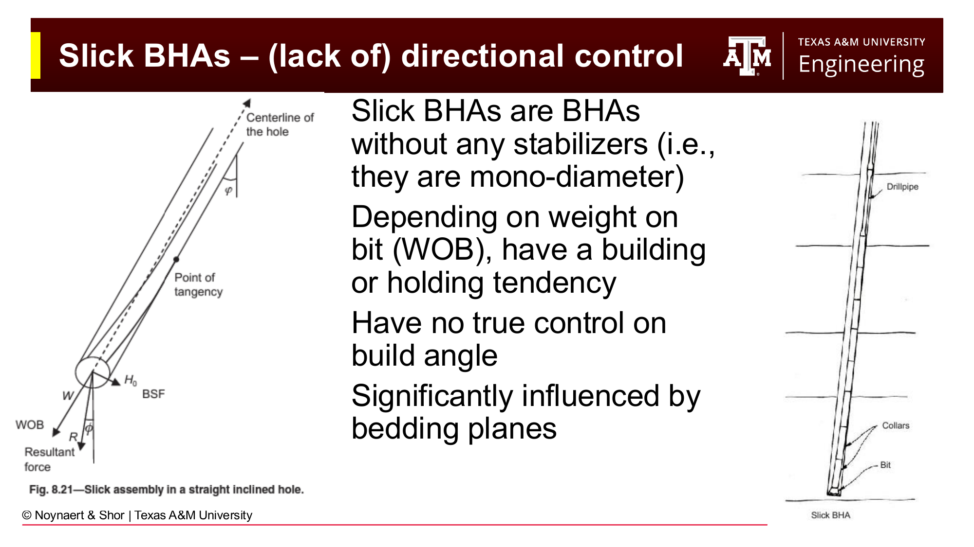
Fig. 163 A slick BHA (no stabilizers) has an unpredictable directional tendency that depends on WOB and formation dip. It has no true directional control.#
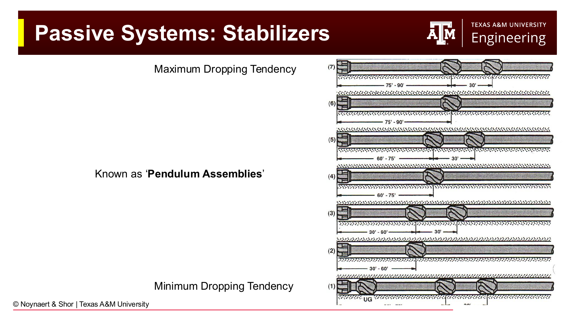
Fig. 164 Pendulum assemblies produce a dropping tendency by placing a stabilizer some distance back from the bit, allowing gravity to pull the bit toward the low side.#
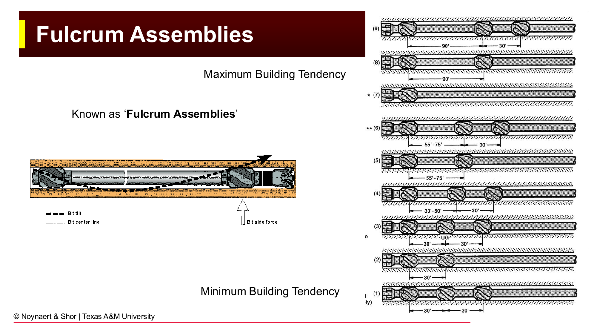
Fig. 165 Fulcrum assemblies produce a building tendency by using a near-bit stabilizer as a fulcrum, leveraging the bit toward the high side.#
Passive assemblies are inexpensive but offer no real-time control. The directional tendency is set by the BHA geometry and can only be changed by pulling the string and re-running a different assembly.
11.6.2 Semi-Active Systems: Mud Motors#
A downhole steerable motor (also called a mud motor, progressive cavity motor, or PDM — positive displacement motor) is a device that converts hydraulic energy from the flowing drilling fluid into mechanical rotation at the bit. It allows the bit to rotate while the drill string above it remains stationary.
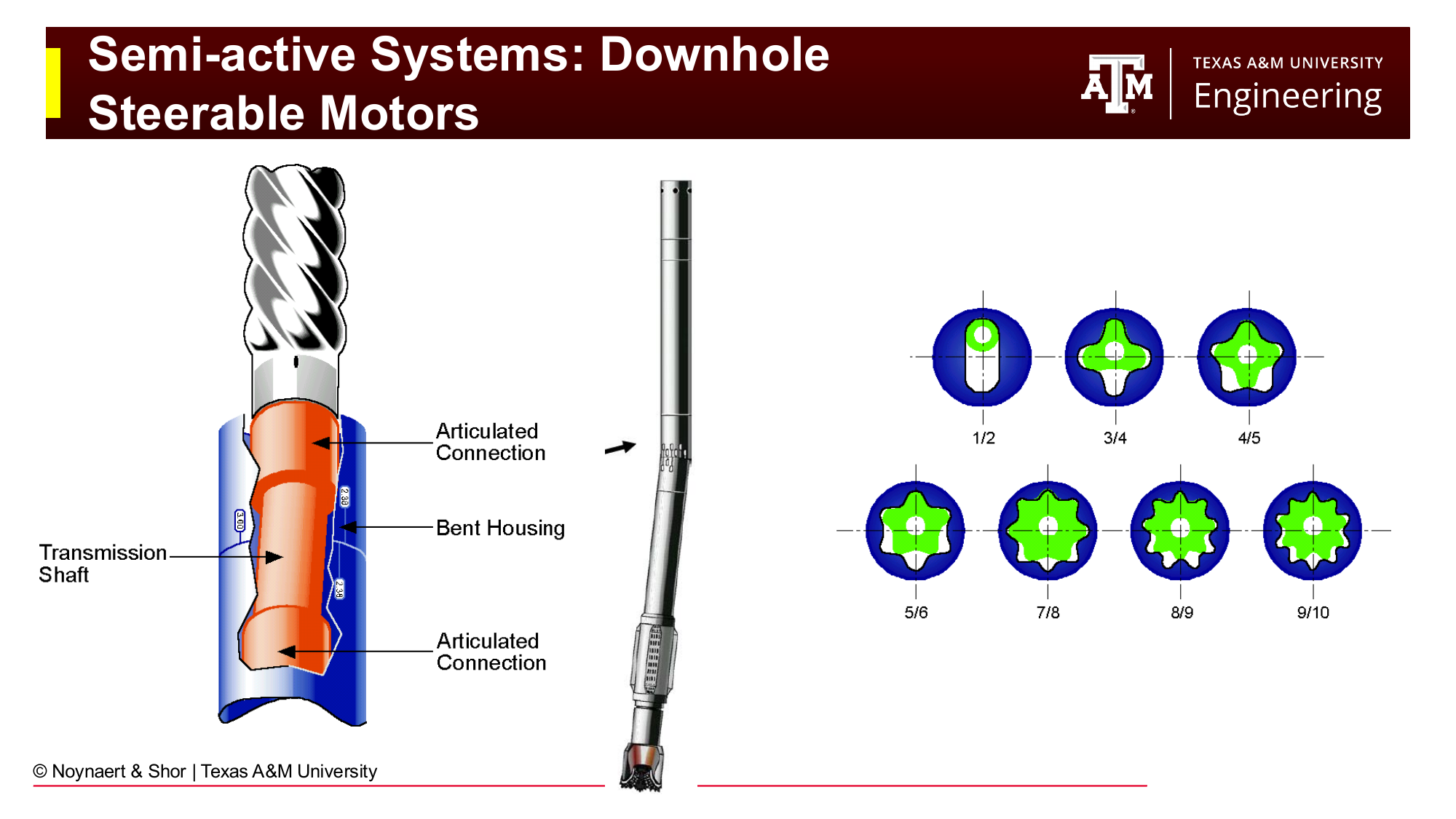
Fig. 166 A downhole motor assembly: the stator is fixed, the rotor turns inside it, and the eccentric motion is converted to rotation at the output shaft and bit.#
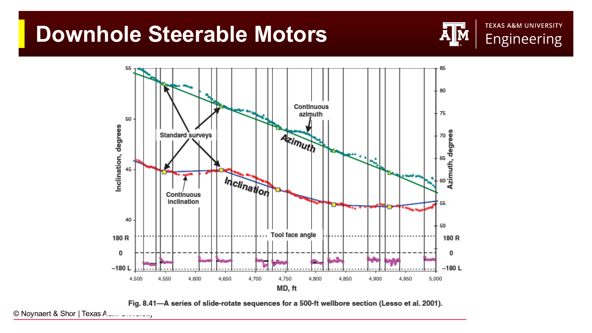
Fig. 167 Detail of a mud motor showing the power section (stator and rotor), flex joint, and bit. A small bend is introduced in the motor housing, typically near the flex joint.#
The directional control comes from a bend built into the motor housing — a slight angle, typically 1–3°, between the motor body and the output shaft. This bend makes the bit point slightly off-axis from the drill string above it.
The motor has two operating modes:
Rotating mode (drill ahead straight): The entire drill string — including the motor housing — is rotated from surface. The bend is spinning with everything else, so over one full rotation the sideload averages out. The well tends to drill straight (or with a very slight spiral).
Sliding mode (steer in a specific direction): The surface rotation is stopped. The motor continues to spin the bit using fluid flow, but the motor housing — and the bend — is held in a fixed orientation. The bit is now consistently pushed in one direction, and the well curves that way. The rate of turn (DLS) is controlled by the size of the bend angle in the motor.
Key Term
In rotating mode, the drill string rotates and the well tends to drill straight. In sliding mode, surface rotation is stopped, the motor housing is oriented with the bend facing the desired direction, and the well curves at the motor’s design DLS.
Mud motor assemblies are widely used on land wells and in many offshore applications. They are less expensive than rotary steerable systems and can achieve high DLS values. Their disadvantage is that the wellbore quality in sliding mode is often lower — the stationary drill string can create a “corkscrew” or “ledgy” borehole as the bit walks and the string moves in discrete surges.
11.6.3 Active Systems: Rotary Steerable Systems (RSS)#
A rotary steerable system (RSS) is a fully active directional drilling tool that steers the wellbore while the entire drill string rotates continuously. There is no sliding mode. The RSS contains a downhole computer and powered actuators that maintain the desired wellbore direction without any change to the surface rotation.
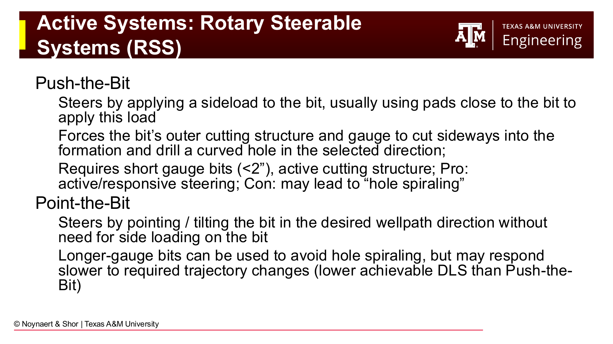
Fig. 168 Rotary steerable systems (RSS) steer the wellbore while the drill string rotates continuously, producing smooth, high-quality wellbores.#
RSS tools use one of two architectural approaches:
Push-the-bit systems apply a sideload directly to the bit by pressing pads against the borehole wall. The pads are positioned to push the bit in the desired direction. Because the sideload forces the outer gauge of the bit to cut into the formation wall, this architecture requires short-gauge bits and produces aggressive steering response. The limitation is that the borehole may exhibit some spiraling.
Point-the-bit systems physically deflect the rotating shaft that drives the bit, tilting the bit toward the desired direction without relying on sideload. Longer-gauge bits can be used, producing smoother boreholes and reducing spiraling. The trade-off is somewhat slower steering response.
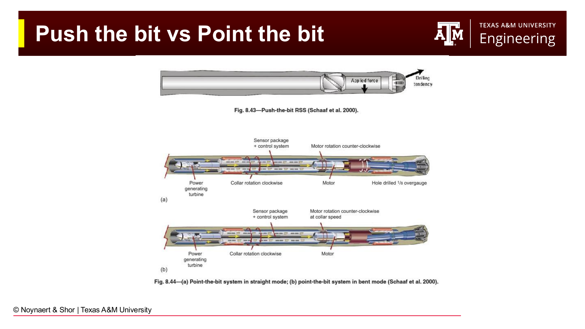
Fig. 169 Push-the-bit RSS (left) applies a sideload to the bit via pads against the borehole wall. Point-the-bit RSS (right) tilts the rotating shaft to redirect the bit without sideload.#
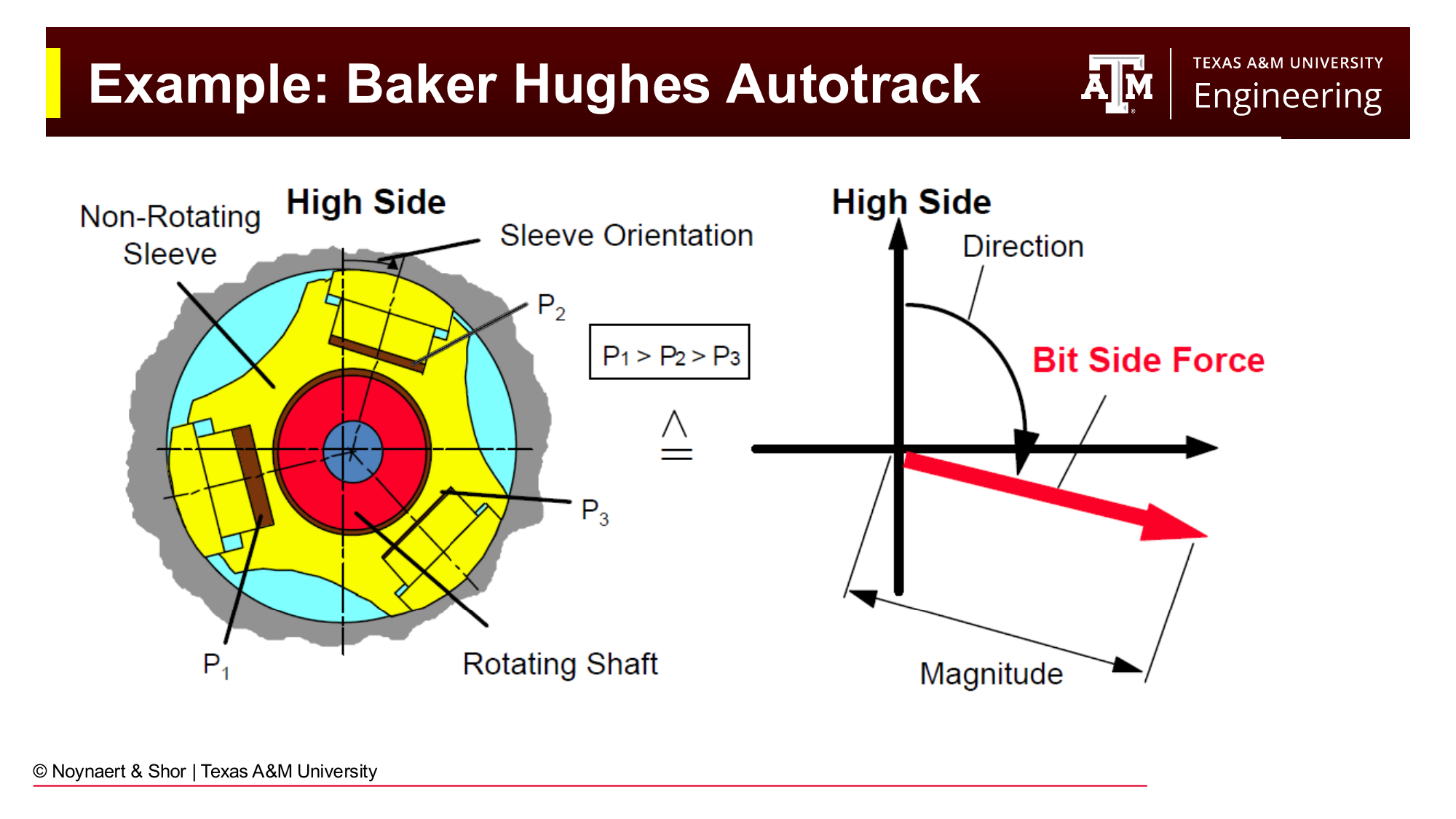
Fig. 170 Cutaway view of a push-the-bit RSS showing the rotating inner shaft, stationary outer housing, and extendable steering pads.#
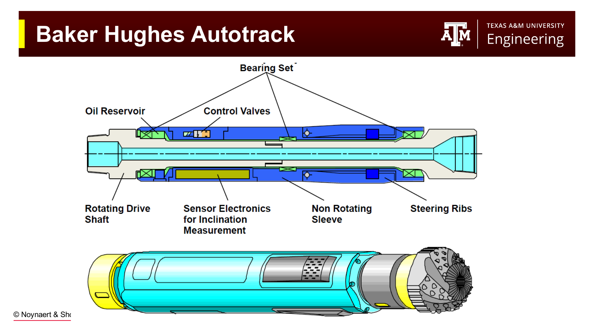
Fig. 171 Rotary steerable tools are sophisticated downhole robots that combine electronics, power generation, and mechanical actuation to steer the wellbore in real time.#
RSS tools produce the smoothest, most predictable wellbores of any directional system. Continuous rotation cleans cuttings from the annulus more effectively, reduces friction and torque, and minimizes the ledging and spiral patterns associated with mud motor sliding. Their disadvantages are cost — an RSS rental is substantially more expensive than a mud motor — and a lower maximum achievable DLS compared to a bent motor at high bend angles. For this reason, most onshore unconventional wells use mud motors (lower cost, higher DLS for tight build sections), while offshore development wells and extended-reach wells frequently use RSS (smoother wellbore, better friction management over long reaches).
11.7 3D Wells#
All the profile shapes described in Section 11.4 are 2D wells: they change inclination but not azimuth (or change azimuth only in a single plane). Real-world drilling often requires 3D wells that change both inclination and azimuth simultaneously, steering through a curved path in three dimensions.
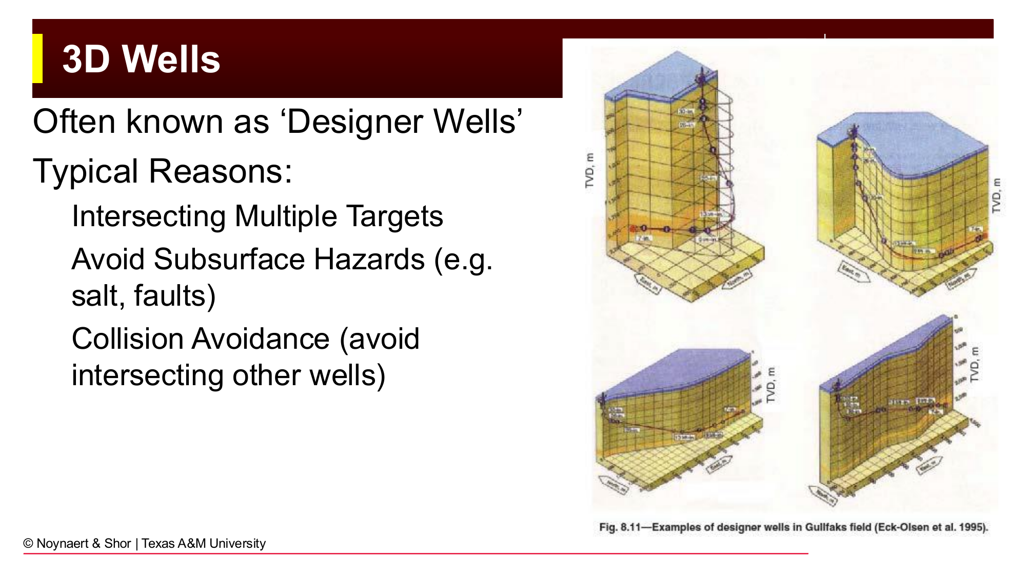
Fig. 172 Three-dimensional “designer” wells change both inclination and azimuth simultaneously, enabling access to targets that cannot be reached by any single-plane trajectory.#
The reasons for 3D trajectories mirror those for directional drilling in general: avoiding subsurface hazards, intersecting multiple targets at different positions in both depth and map location, managing stress orientation in the reservoir, and collision avoidance in crowded offshore fields. As computing power has made 3D trajectory design routine, the range of achievable well geometries has expanded dramatically. Horseshoe wells — where a horizontal well makes a complete 180° turn underground and returns as a second parallel horizontal — were considered impractical a decade ago and are now drilled routinely.
The Mars A-18 platform in the Gulf of Mexico illustrates a real-world 3D development scenario. Multiple wells radiate from the platform, each deviating in different azimuth directions and at different rates to reach oil and gas targets trapped in the wing structures of a large deepwater salt dome.
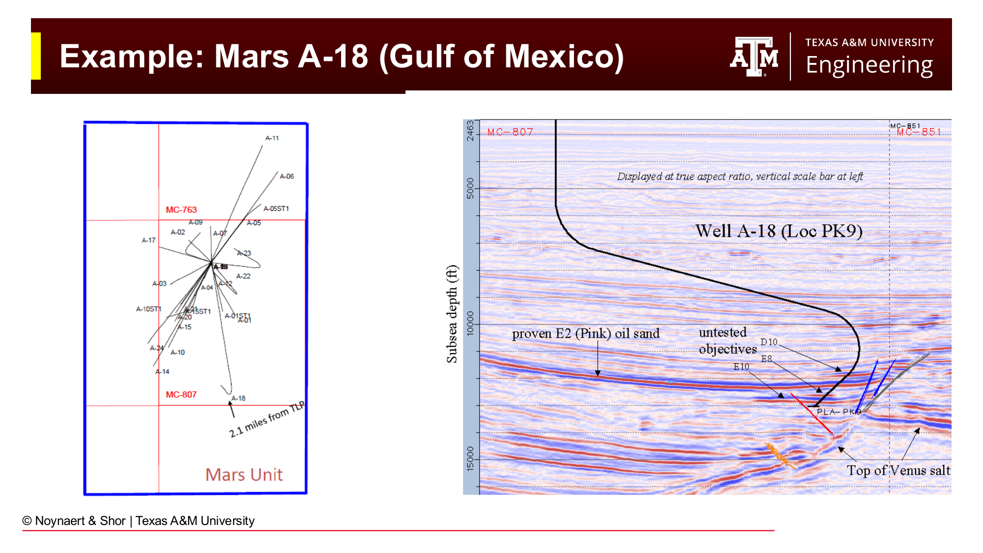
Fig. 173 The Mars A-18 platform in the Gulf of Mexico — multiple directional and 3D wells access reservoir targets in the wing structures of a subsalt formation.#
11.8 Worked Examples#
Example 11.1 — Identifying and Describing a Well Profile#
Given: A well has the following planned wellbore survey:
MD (ft) |
INC (°) |
AZ (°) |
|---|---|---|
0 |
0 |
0 |
3,000 |
0 |
0 |
3,400 |
40 |
270 |
6,000 |
40 |
270 |
6,400 |
0 |
90 |
9,000 |
0 |
90 |
Required: (a) What profile type is this well? (b) What direction does the well point during its deviated section? (c) What is the DLS through the build and drop sections? (d) What happened between MD = 6,000 ft and MD = 6,400 ft that caused the azimuth to change from 270° to 90°?
Solution:
(a) Profile type:
The well goes from 0° inclination at MD = 0–3,000 ft (vertical), builds to 40° between 3,000 and 3,400 ft, holds 40° from 3,400 to 6,000 ft, then drops back to 0° between 6,000 and 6,400 ft, and continues vertically from 6,400 to 9,000 ft. This is an S-type well: vertical → build → tangent → drop → vertical.
(b) Direction of the deviated section:
During the tangent section (MD = 3,400 to 6,000 ft), the azimuth is 270°. An azimuth of 270° corresponds to due west.
(c) DLS through build and drop:
Both the build and drop sections cover 400 feet of MD and change inclination by 40°:
(d) Azimuth change interpretation:
The azimuth went from 270° (west) during the tangent to 90° (east) in the final vertical section. The inclination dropped from 40° back to 0°. For the inclination to return to zero, the well had to continue turning — past vertical — in the same rotational direction it had been building. When a well passes through vertical (inclination crosses 0°), the azimuth reverses by 180°, because the well is now pointing the opposite direction.
The well did not turn 180° sideways; it dropped through vertical, which automatically reverses the reported azimuth. This is a normal artifact of the inclination/azimuth convention and does not represent an actual change of direction in the subsurface.
Example 11.2 — Dogleg Severity and Radius of Curvature#
Given: A horizontal well is planned with a build section from 0° to 90° inclination. The available directional tool is a mud motor assembly capable of a maximum DLS of 8°/100 ft.
Required: (a) What is the radius of curvature of the build section? (b) What is the minimum measured length of drill string required to build from 0° to 90°? (c) How deep must the KOP be to ensure the well is drilling horizontal before it reaches TVD = 8,500 ft?
Solution:
(a) Radius of curvature:
(b) Minimum arc length of the build:
The arc length for a 90° turn on a circle of radius \(R\) is one quarter of the circumference:
Alternatively, using the relationship between DLS and arc length:
(The two methods agree, with minor rounding difference.)
(c) Required KOP depth:
During a 90° build, the TVD gained is the vertical component of the circular arc from 0° to 90°:
Wait — this formula applies to the vertical drop from the chord across a quarter circle. The correct formula for TVD gained through the build section (from inclination \(\alpha_1\) to \(\alpha_2\)) is:
For the well to be horizontal (90° inclination) at TVD = 8,500 ft:
The KOP must be set no deeper than TVD = 7,784 ft for the well to be horizontal before reaching the target TVD.
Example 11.3 — Selecting a Directional System#
Given: An operator is planning three wells:
Well A: A 12,000-ft vertical well that has deviated off course by 3°. The engineer wants to correct back to vertical over 500 ft.
Well B: An offshore extended-reach well with a planned horizontal departure of 18,000 ft. The well is 10,000 ft TVD, has a 5°/100 ft build to horizontal, and will have a 9,000-ft horizontal lateral. The operator needs the lowest possible torque and friction.
Well C: An onshore shale horizontal well, 8,000 ft TVD to KOP, 8°/100 ft build to horizontal, 7,500-ft lateral. Cost is the primary driver.
Required: For each well, identify the most appropriate directional system and justify the recommendation.
Solution:
Well A: A simple correction of 3° over 500 ft requires a DLS of \(3°/500 \text{ ft} \times 100 = 0.6°/100 \text{ ft}\) — a trivially gentle correction. A stabilizer-based passive assembly (adjusting stabilizer placement) is sufficient and costs nothing beyond the normal BHA. No dedicated directional tool is needed for such a mild correction.
Well B: With 18,000 ft of horizontal departure and a 9,000-ft lateral, torque and drag management are critical. Continuous string rotation throughout the well minimizes friction (because sliding a stationary string generates far higher friction than rotating it) and keeps the annulus cleaner. A rotary steerable system (RSS) is the correct choice. The additional rental cost is justified by the ability to drill the extended reach at all — a mud motor in sliding mode might not be able to deliver adequate WOB to the bit at such depths because friction would absorb most of the applied weight.
Well C: A typical onshore shale horizontal with no extreme reach requirements. The 8°/100 ft build rate is well within the capability of a standard bent motor mud motor assembly. With cost as the primary driver, a mud motor assembly is the right choice. The slightly rougher wellbore and the need to slide through the build section are acceptable compromises for the significantly lower rental cost compared to RSS.
11.9 Practice Problems#
Problem 11.1 — A directional driller reports a DLS of 12°/100 ft in the build section of a well. What is the radius of curvature of this section in feet? If the well builds from 0° to 60°, what is the arc length of drill string in the build section?
Solution
Radius of curvature:
Arc length of build:
Check via arc geometry: \(\text{arc} = \frac{60}{360} \times 2\pi \times 477.5 = \frac{\pi \times 477.5}{3} = 500 \text{ ft}\) ✓
Problem 11.2 — A planned build-and-hold well has its KOP at 4,200 ft TVD. The DLS is 6°/100 ft. The target inclination is 30°. Calculate (a) the measured length of the build section, (b) the TVD gained during the build, and (c) the horizontal departure gained during the build.
Solution
Radius of curvature: $\(R = \frac{5729.6}{6} = 954.9 \text{ ft}\)$
(a) Measured length of build: $\(\text{MD}_\text{build} = \frac{30^\circ}{6^\circ/100\text{ft}} \times 100 = 500 \text{ ft}\)$
(b) TVD gained during build (inclination goes from 0° to 30°): $\(\Delta TVD = R(\sin 30^\circ - \sin 0^\circ) = 954.9 \times 0.5 = 477.5 \text{ ft}\)$
(c) Horizontal departure gained during build (inclination goes from 0° to 30°): $\(\Delta HD = R(1 - \cos 30^\circ) = 954.9(1 - 0.866) = 127.9 \text{ ft}\)$
At the end of the build section, the well is at TVD = 4,200 + 477.5 = 4,677.5 ft, and has moved 127.9 ft horizontally.
Problem 11.3 — A wellbore survey from a vertical well shows the following:
MD (ft) |
INC (°) |
AZ (°) |
|---|---|---|
0 |
0 |
0 |
2,000 |
0 |
0 |
5,200 |
45 |
90 |
8,200 |
45 |
90 |
What profile type is this well? What direction is the tangent section pointing? What is the DLS of the build? In what general compass quadrant is the surface location relative to the subsurface target?
Solution
Profile type: Build-and-hold. The well drills vertically to 2,000 ft, then builds from 0° to 45° over 3,200 ft, then holds 45° for the final 3,000 ft.
Direction of tangent: Azimuth 90° = due east.
DLS of build: $\(\text{DLS} = \frac{45^\circ}{3200\text{ ft}} \times 100 = 1.4°/100\text{ ft}\)$
Compass quadrant: The well is traveling east and downward. Therefore the target is to the east of the surface location.
Problem 11.4 — An operator needs to access a reservoir target located 5,000 ft horizontally from the drilling location and at 10,000 ft TVD. The formation below the KOP is difficult to drill directionally, limiting the DLS to 4°/100 ft. Should the KOP be placed shallower or deeper to ensure the well can reach its target? Estimate the minimum required KOP depth, assuming the well will build to 60° and drill a tangent to the target.
Solution
Radius of curvature: $\(R = \frac{5729.6}{4} = 1432.4 \text{ ft}\)$
TVD gained during build (0° to 60°): $\(\Delta TVD_\text{build} = R(\sin 60° - \sin 0°) = 1432.4 \times 0.866 = 1240.5 \text{ ft}\)$
Horizontal departure during build: $\(\Delta HD_\text{build} = R(1 - \cos 60°) = 1432.4(1 - 0.5) = 716.2 \text{ ft}\)$
Remaining target parameters after build:
Remaining TVD: \(10000 - TVD_{KOP} - 1240.5\)
Remaining HD: \(5000 - 716.2 = 4283.8 \text{ ft}\)
On the tangent at 60°: $\(\frac{\Delta TVD_\text{tangent}}{\Delta HD_\text{tangent}} = \frac{\cos 60°}{\sin 60°} = \cot 60° = 0.577\)$
Solving for KOP TVD: $\(TVD_\text{KOP} = 10000 - 1240.5 - 2473.5 = 6286 \text{ ft}\)$
The KOP must be set no deeper than approximately 6,286 ft TVD. Setting it shallower gives more room to complete the build and reach the target; placing it deeper would leave insufficient TVD to both build angle and cover the required horizontal departure.
Problem 11.5 — A company is evaluating two directional systems for a horizontal shale well: a mud motor bent assembly (DLS capability: 15°/100 ft, tool rental: \(500/day) and a push-the-bit RSS (DLS capability: 8°/100 ft, tool rental: \)2,500/day). The well has a 9,000-ft build section and a 6,000-ft lateral. Estimated drilling rates: 75 ft/hr in the build, 150 ft/hr in the lateral. The operator requires a KOP-to-lateral depth of exactly 5,000 ft TVD, which means the build to 90° needs to fit within the available depth.
(a) Can both tools complete the 90° build to horizontal? What is the arc length required for each?
(b) For each tool, estimate total tool rental cost for the directional portion of the well (build + lateral, assuming no time lost).
(c) What factors beyond cost should influence the decision?
Solution
(a) Build arc lengths:
Mud motor (15°/100 ft): \(\text{MD}_\text{build} = \frac{90}{15} \times 100 = 600 \text{ ft}\); \(R = 5729.6/15 = 382 \text{ ft}\); TVD gained \(= 382 \text{ ft}\) — fits well within 5,000 ft. ✓
RSS (8°/100 ft): \(\text{MD}_\text{build} = \frac{90}{8} \times 100 = 1125 \text{ ft}\); \(R = 5729.6/8 = 716 \text{ ft}\); TVD gained \(= 716 \text{ ft}\) — also fits within 5,000 ft. ✓
Both tools can complete the build.
(b) Rental cost estimates:
Mud motor:
Build time: \(600 \text{ ft} / 75 \text{ ft/hr} = 8.0 \text{ hr}\)
Lateral time: \(6000 \text{ ft} / 150 \text{ ft/hr} = 40 \text{ hr}\)
Total: 48 hr = 2.0 days × \(500/day = **\)1,000**
RSS:
Build time: \(1125 \text{ ft} / 75 \text{ ft/hr} = 15.0 \text{ hr}\)
Lateral time: \(6000 \text{ ft} / 150 \text{ ft/hr} = 40 \text{ hr}\)
Total: 55 hr = 2.3 days × \(2,500/day = **\)5,750**
The RSS costs roughly 5.75× more for tool rental in this scenario.
(c) Other decision factors:
Wellbore quality: The RSS produces a smoother, less spiraled wellbore, which reduces friction in completions and production operations.
Casing running: A smoother wellbore is easier to run casing or a cemented liner into. The extra build-section length of the RSS (1,125 ft vs. 600 ft) is a longer, gentler curve that is inherently easier to run tubulars through.
Sliding difficulty: Mud motors require sliding to steer. If the lateral is at high inclination (90°), sliding drill string for steering corrections is difficult and slow. RSS maintains continuous rotation, which is far better for steering in long horizontals.
Shale type: Soft, gummy shales may make it difficult to slide a mud motor. RSS would be preferred.
Total well economics: In a 6,000-ft lateral, the difference in tool cost ($4,750) may be small relative to the value of better wellbore placement (hitting the sweet spot of the formation) or reduced completion costs from a smoother bore.
Chapter Summary#
Directional drilling is not a niche specialty — it is the standard mode of drilling for the modern industry. Most wells drilled today depart from vertical, and horizontal wells in shale and tight formations have transformed the energy landscape of the past two decades.
The geometric framework for describing directional wells centers on five quantities measured or calculated at every survey station: measured depth (MD), true vertical depth (TVD), inclination, azimuth, and horizontal departure. From these, northing and easting provide the full 3D position. The wellbore survey is the record of these quantities and is the primary navigation tool for the directional driller.
Well profiles are classified as build-and-hold, S-type, or continuous build, and are characterized by the kickoff point depth, dogleg severity (DLS), and target inclination. The radius of curvature \(R = 5729.6 / \text{DLS}\) connects the DLS to the geometry of the curved section and is the fundamental parameter for calculating TVD and horizontal departure through the build.
Directional drilling systems range from passive (whipstocks, stabilizer assemblies) to semi-active (mud motors) to active (rotary steerable systems). Mud motors are the workhorse of onshore directional drilling — flexible, capable of high DLS, and cost-effective. Rotary steerable systems produce the smoothest wellbores and the best friction management for extended-reach and offshore wells, at a higher rental cost. The selection of the appropriate system is an engineering trade-off between DLS requirement, wellbore quality, reach, and economics.
Chapter 12 presents the quantitative calculation methods for translating wellbore surveys into 3D position coordinates.
Key Equations#
Quantity |
Formula |
|---|---|
Radius of curvature |
\(R (\text{ft}) = \dfrac{5729.6}{\text{DLS} \, [^\circ/100\text{ft}]}\) |
Build arc length |
\(\text{MD}_\text{build} = \dfrac{\Delta \text{INC} \, [^\circ]}{\text{DLS} \, [^\circ/100\text{ft}]} \times 100 \text{ ft}\) |
TVD through build |
\(\Delta TVD = R(\sin \alpha_2 - \sin \alpha_1)\) |
HD through build |
\(\Delta HD = R(\cos \alpha_1 - \cos \alpha_2)\) |
TVD through tangent |
\(\Delta TVD = L \cos \alpha\) |
HD through tangent |
\(\Delta HD = L \sin \alpha\) |
Horizontal displacement |
\(HD = \sqrt{(\Delta N)^2 + (\Delta E)^2}\) |
Where \(\alpha\) is inclination in degrees, \(L\) is the measured length of the tangent section, and \(\alpha_1\), \(\alpha_2\) are the inclinations at the start and end of a curved section.