Chapter 22: The Drilling Engineer and the Drill Well on Paper (DWOP)#
Learning Objectives#
By the end of this chapter, students should be able to:
Describe the role of the drilling engineer within the overall well delivery team.
Identify the key parties in a drilling operation: the operator, drilling contractor, service companies, and consultants, and explain each party’s responsibilities and liabilities.
Define a Drill Well on Paper (DWOP) and explain its purpose in the well planning process.
List and explain the six standard components of a DWOP.
Read and interpret a days vs. depth plot.
Identify how the different technical subjects covered in this e-book, geomechanics, casing design, well control, directional drilling, and drilling fluids, fit together within a single well planning document.
22.1 What Does a Drilling Engineer Do?#
Every chapter in this book has, in some sense, been preparation for this one. Geomechanics tells you what rocks you will drill through and how they will behave. Drilling fluids keep the hole stable. Hydraulics governs the pressure at depth. Well control is what you do when something goes wrong. Directional drilling gets you where the reservoir is. Casing and cementing protect everything you drilled. A drillbit and a drillstring drill the actual hole. A drilling engineer is the person who brings all of this together.
The drilling engineer is the technical hub of the well delivery operation. They collect information from geologists, geophysicists, petrophysicists, reservoir engineers, and a long list of service company specialists. From that information, they design the wel, the casing program, the fluid system, the directional plan, the drill string, and the operational sequence, and then translate that design into a set of documents that everyone involved in drilling the well can work from.
The drilling engineer does not show up at the rig with a wrench, nor do they sit in the driller’s chair. Their job is planning, design, and oversight. When a decision has to be made during drilling: change the mud weight, call for a survey, set an extra casing string, it is the drilling engineer who is called. And when something goes wrong, the engineering choices made before the well was drilled become evidence in a conversation about who is responsible.
22.2 The Drilling Team#
A drilling operation involves several distinct organizations with different assets, expertise, and legal standing. Understanding who they are and what they bring is essential context for the drilling engineer.
22.2.1 The Operator#
The operator is the company whose lease it is: the entity that holds the mineral rights, has a legal obligation to produce (or explore), and takes ownership of whatever comes out of the well. The operator is ultimately financially responsible for the well. If a downhole tool is lost and cannot be recovered, the operator pays the replacement cost unless they can prove that another party’s negligence caused the loss. If the well blows out, the cleanup is the operator’s problem.
The operator typically brings geological and reservoir knowledge. They understand the stratigraphy, know what formation pressure is expected, have looked at the seismic, and have a vision of what the well is supposed to accomplish. They will also have a drilling engineering team, one engineer or a small group, who are responsible for the overall well design.
22.2.2 The Drilling Contractor#
The drilling contractor is the company that shows up with the rig. The analogy is instructive: a drilling contractor is like the company that arrives at a construction site with a crane. They bring the crane, they know how to operate it, and they provide the trained crew to run it. They do not bring the materials that the crane will lift, and they do not have opinions about what the building will look like when it is done.
The rig is the primary asset: it provides the mechanical systems (drawworks, rotary table or top drive, traveling block, derrick) to lower and raise the drill string, rotate it, and apply weight to the bit. The drilling contractor will also bring a driller, who is the person at the controls during drilling operations, and a crew of floor hands, derrickmen, and other rig personnel.
Many drilling contractors supply standard drill pipe. Some provide surface equipment such as the standpipe manifold or choke manifold. What they almost never supply is the drilling fluid system, that is a separate service, or, historically, the directional driller. Depending on the contracting structure, they may or may not have a mud engineer on staff.
22.2.3 Service Companies#
A large number of specialized service companies operate alongside the operator and drilling contractor. Service companies supply:
Drilling fluids: mixing, monitoring, and adjusting the mud system throughout the well
Drill bits: selecting, supplying, and evaluating bit performance
Directional drilling: supplying the directional driller and the tools (measurement-while-drilling equipment, mud motors, rotary steerable systems) needed to steer the well
Cementing: supplying cement, mixing equipment, and the personnel to execute primary and remedial cementing
Logging: running wireline tools or MWD/LWD equipment to characterize the formations drilled
A critical point about downhole tools supplied by service companies: the tools are typically leased, not sold. The service company owns the measurement tools, the motors, the jars, the specialty BHA components. When the tool is pulled out of the hole, it goes back to the service company. If it is damanged beyond repair (DBR) or not pulled out, if it is stuck, dropped, or otherwise lost downhole, the operator typically bears the financial responsibility, because the operator controls the well.
22.2.4 Consultants#
For complex or high-risk wells, the operator will often bring in independent consultants who have specialized knowledge of a particular formation, geographic area, or type of operation. Consultants serve two functions: they can assist with aspects of the design that exceed the operator’s in-house expertise, and they can serve as an independent check on the drilling engineer’s work. A common workflow is for the drilling engineer to prepare the well design and then send it to a consultant for review. The consultant will identify potential issues, request modifications, or confirm that the design appears sound.
22.3 Liability and the Daily Drilling Report#
Because multiple organizations share the wellsite, and because the wellsite is a place where expensive things can go wrong, the industry has developed formal mechanisms for recording what happened and establishing who was responsible.
The daily drilling report (DDR) is the central record. Every day on a drilling operation, the operator’s company man (their on-site representative) and the drilling contractor’s driller document in detail what occurred: the bit depth, the formation drilled, the mud weight, the time spent on each operation, any problems encountered, and decisions made. These reports are legally significant documents. If a BHA is lost downhole and there is a question of fault, the daily drilling reports are the first thing everyone reads.
Establishing fault is rarely simple. Consider a scenario where the driller is pushing toward a performance target set by the operator’s drilling engineer, drilling as fast as possible, staying on schedule, and the drill string parts. The driller had their hands on the controls. But if the drill string parted because it was under-designed for the loads it experienced, responsibility shifts toward the drilling engineer who specified it. If the drill string was correctly designed but the driller was operating outside the parameters specified in the drilling program, responsibility shifts back.
This ambiguity is one reason why clear communication before drilling begins is critical. If the drilling team understands the risks, the constraints, and the objectives, and that understanding is documented, then everyone can make better decisions in real time, and the record is clearer when things go wrong.
22.4 What Is a Drill Well on Paper (DWOP)?#
A Drill Well on Paper (DWOP) is a structured planning meeting and document, prepared and held before drilling begins, in which all interested parties: the operator, the drilling contractor, and the major service companies, assemble to review the well plan in full detail and get on the same page about objectives, methods, schedule, and risks.
The name is literal: in this meeting, you drill the well on paper. You walk through every section, every operation, every decision point, as if you were drilling the well right now, but without having to actually be in the hole. The goal is to surface problems, miscommunications, and missing information before they become problems in the hole.
A DWOP serves several distinct functions:
Communication: Contractors who will be on site learn what the well is trying to accomplish, what the geology looks like, what unusual operations are planned, and what has gone wrong on previous nearby wells. Knowledge that lives in the operator’s files reaches the people who need it.
Planning review: The well design is presented in enough detail that everyone can identify gaps or conflicts. A cementing contractor may point out that the proposed casing shoe depth puts them in a depleted zone that will affect cement returns. A directional driller may flag that the planned dogleg severity is at the limit of what the selected motor can achieve.
Schedule coordination: The days vs. depth plot (discussed below) tells every party when they are expected to be on site. A specialist brought in for a logging run, a geologist who wants to be present during a coring operation, or a pressure test team all need to know when to show up. The DWOP schedule is the official reference.
Risk identification: Known hazards: lost circulation zones, shallow gas, a tight casing annulus for a specific section, high vibration expected in a hard formation, are discussed so that the entire team can watch for early warning signs and respond appropriately.
22.5 Components of a DWOP#
A complete DWOP document typically contains six major components.
22.5.1 Program Objectives#
The first question a DWOP must answer is: what is this well trying to accomplish? The answer shapes every subsequent decision.
Is this an exploration well (a wildcat) looking for a new hydrocarbon accumulation? A development well in a mature field? An infill well to increase recovery from an existing reservoir? A geothermal well targeting hot rock? A CO₂ injection well? An observation well for micro-seismic monitoring?
The answer affects the geological uncertainty the team is working with, the acceptable level of risk, the performance metrics used to evaluate success, and which parties need to be present at which times.
For example, an exploration well has much higher geological uncertainty than a development well. The stratigraphy column may be inferred from surface outcrops or regional correlations rather than from offset wells in the same field. Surface outcrops provide some indication of rock type and sequence, but the chemistry, the pore fluid, and the stresses underground can differ substantially from what outcrop samples suggest. The DWOP for an exploration well must acknowledge this uncertainty and plan for it explicitly.
22.5.2 Site and Geological Information#
This section of the DWOP presents the information the team needs to understand the subsurface they will be drilling into. It covers:
Location: Where is the well? Maps showing the site, nearby infrastructure, existing wellheads, and geological structures help orient the whole team.
Stratigraphy: What formations will be drilled, in what order, and with what expected thicknesses? What are the lithologies — sandstone, shale, carbonates, evaporites, igneous rock?
Pore pressure and fracture gradient profile: The drilling window for each section is derived from this profile. Setting depths for casing depend on it.
Formation temperatures: Temperature at depth affects tool survival, mud chemistry, and cement hydration. Wells targeting geothermal resources, in particular, may approach or exceed the temperature limits of standard downhole electronics (typically around 275°F).
Known hazards: Lost circulation zones, shallow gas, H₂S-bearing formations, high-pressure zones, or mechanically unstable intervals should all be flagged.
Learnings from offset wells: If wells have been drilled nearby, what problems were encountered? What worked better than expected? Caliper logs from previous wells can reveal borehole quality issues. Drilling reports can identify formations that gave trouble.
22.5.3 Well Design Summary#
The drilling engineer presents the core of the technical design:
Well trajectory: Is the well vertical, deviated, horizontal, or S-shaped? What is the kickoff point, build rate, and landing target? For wells drilled near existing wellbores, collision avoidance analysis is included here.
Casing and liner program: How many strings are run, at what depths, and in what sizes? This section shows the complete wellbore architecture.
Cementing program: What cement is used for each string? What are the designed top-of-cement depths? What spacer and preflush program is planned?
Drill string design: What BHA components are planned for each hole section? Bit type, stabilizers, MWD/LWD tools, mud motor or rotary steerable, heavy-weight drill pipe, and drill collars.
Drilling fluid program: What mud type (WBM, OBM, SBM) is used for each section? What mud weight? What additives, and why? What special considerations exist for the formation (shale swelling, lost circulation, differential sticking)?
22.5.4 Operational Program#
For each hole section, the conductor, surface hole, intermediate, production, the DWOP provides a step-by-step description of planned operations:
Drill out cement, confirm shoe integrity
Drill to planned casing point, circulate bottoms up
Run logs
Run casing, cement
Nipple up BOP, pressure test
This operational sequence is how the drilling contractor’s team knows what to do next, and how service companies know when they are needed. It is also where unusual operations are flagged: a formation integrity test (FIT) or extended leak-off test (XLOT) to characterize stress, a coring run, or a special BHA that changes the operating parameters the driller monitors.
22.5.5 The Days vs. Depth Plot#
The days vs. depth plot (also called the drilling schedule or time-depth plot) is one of the most practically useful outputs of the DWOP. On this plot, the horizontal axis is calendar time (in days from spud) and the vertical axis is depth.
Reading the plot:
Diagonal sections: the well is making hole (drilling). Steeper = faster drilling.
Flat sections: depth is not changing. This is time spent on non-drilling operations: running casing, cementing, running BOP, pressure testing, logging, conducting formation tests, or waiting on equipment.
The flat sections, called “flat time,” are where rigs spend a surprisingly large fraction of total well time, and where schedule optimization often focuses.
The days vs. depth plot shows the planned schedule: the optimistic scenario in which everything goes more or less as designed. The actual well will almost always look different. Trips due to a worn bit, equipment repairs, weather events, reaming runs through tight spots, or waiting on third-party services all add flat time that was not planned. The value of the plot is not that it will be accurate in detail, but that it establishes a shared reference and communicates when each party should plan to be on site.
22.5.6 Special Operations and Risk Identification#
The DWOP explicitly documents anything unusual about this well that might catch an experienced driller off guard. Examples include:
Non-standard BHA components: A particle-jet drilling assembly, an acoustic data-puck, or a fiber-optic sensor system all change what the driller sees at surface and what parameters they should monitor.
Fiber behind casing: If fiber optic cable is being installed behind a casing string, the casing cannot be rotated during installation. If the casing gets stuck, reciprocation is the only option; rotation is off the table. This must be communicated explicitly.
Coring: The coring BHA is run to collect a sample of the formation. If the coring bit is smaller than the main hole (as in some geothermal programs), a reaming run must follow to restore full hole size. Reaming is a high-vibration operation and may require removing sensitive downhole tools first.
Temperature extremes: Geothermal wells may reach temperatures at or beyond standard tool limits. The team needs a plan for monitoring and managing thermal effects on drilling fluid behavior and downhole electronics.
Pipe-light conditions: In MPD operations with high back pressure, the buoyancy on the drill string increases. If back pressure is high enough, the string weight displayed at surface can go to zero or negative: a hazardous condition called pipe-light. The driller must know this is possible and what to do.
Identified risks are not meant to be alarming; they are meant to be managed. A driller who knows that a specific interval historically causes vibration-related BHA damage will monitor vibration parameters more carefully and respond earlier. A cementer who knows a tight annulus is expected will design a lower-rate displacement program. Knowing the risk in advance is almost always better than discovering it in real time.
22.6 Case Study: The Utah FORGE DWOP#
To make the above concrete, it is worth walking through a real example. Utah FORGE (Frontier Observatory for Research in Geothermal Energy) is a Department of Energy-funded test site in central Utah investigating enhanced geothermal systems (EGS). Because DOE funding requires public disclosure, all FORGE data, including the full video recording of DWOP meetings, is publicly available, making it an unusually transparent look at how the industry actually plans a well.
The DWOP discussed here covers well 16B(78)-32, drilled in early 2023. The designation encodes location information in the style common to publicly-traded U.S. leases: a combination of geographic coordinates and well number. The “16B” indicates that this is the second (B) well in the 16-series at FORGE. The objective was to drill a well that, in combination with the previously completed 16A, would form a well pair, two parallel wells separated by a designed distance, between which hydraulic fractures could be created and flow tested.
Objectives: The program had multiple simultaneous objectives: (1) land the well parallel to and at a designed spacing from 16A, (2) collect vibration data using downhole sensor pucks to characterize and reduce tool damage in granite, (3) test a particle-jet drilling assembly, (4) conduct stress characterization tests, and (5) collect core from specific intervals.
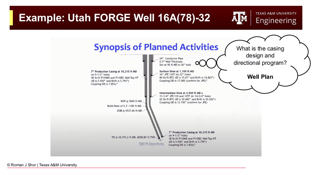
Fig. 266 The well plan from the publicly available Utah FORGE DWOP: conductor, 16-in surface casing at 1,100 ft, 11¾-in intermediate at 4,960 ft, KOP at 5,600 ft with a 5.5°/100 ft build, and 7-in production casing at 10,215 ft MD with 500 ft of open hole to TD.#
Geological considerations: FORGE sits in the transition zone between the basin-and-range terrain and the Colorado Plateau. The target horizon is crystalline granite at approximately 8,000 ft depth, where temperatures reach around 300°F. Most standard downhole electronics are rated to 275°F, so the team was operating right at the thermal boundary. Unlike sedimentary rocks, granite is crystalline and homogeneous: fractures propagate differently in it, and the familiar drill-bit experience (weight on bit, torque response) is different from sedimentary basins.
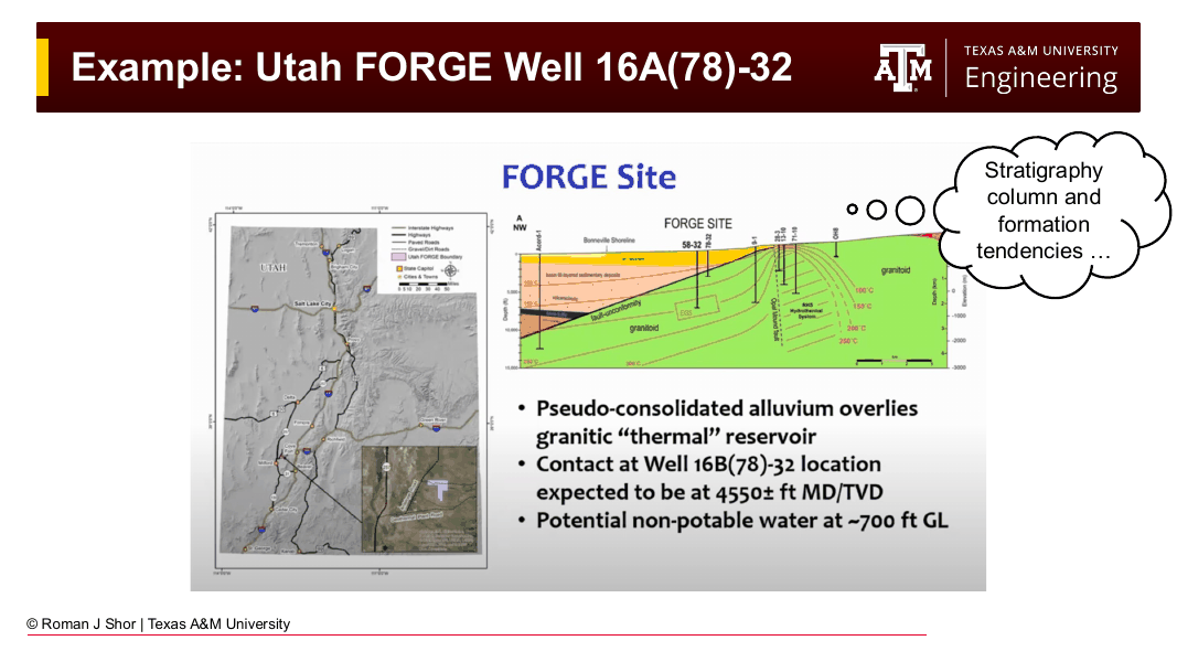
Fig. 267 Site and geological information from the FORGE DWOP: location maps and the geologic cross-section showing pseudo-consolidated alluvium over the granitoid thermal reservoir, with the alluvium-granite contact expected at ~4,550 ft and isotherms defining the EGS target.#
Learnings from 16A: The caliper log from the previously drilled 16A showed a highly tortuous borehole; not random, but periodic. The periodicity came from the team’s rotate-slide-rotate pattern with a bent motor assembly: every slide interval pushed the bit off-center, and every rotate interval averaged back toward centerline, creating a sinusoidal borehole shape. This pattern increases torque and drag, makes casing running harder, and requires larger casing-to-borehole clearances. For 16B, the directional drilling plan needed to account for this: whether by accepting the same tortuosity pattern or by switching to a rotary steerable system.
Collision avoidance: Because 16B was designed to run parallel to 16A at close spacing, the directional program had to include an anti-collision analysis. Two wells on the same lease running near each other must be tracked and surveyed carefully to ensure they do not intersect. An accidental collision between wells — though rare — is dangerous and expensive.
Special operations: The DWOP documented several non-standard elements:
The particle-jet BHA injects a high-speed slurry to erode rock rather than rotating against it. Operating parameters (flow rate, fluid density, WOB, RPM) are very different from a conventional drill bit, and the driller needs to know what normal looks like for this system before troubleshooting begins.
The data puck — a ruggedized 9-axis inertial measurement unit — recorded vibration throughout drilling. Its survival was one of the explicit objectives, meaning vibration limits had to be incorporated into the drilling parameters.
Fiber optic cable was installed behind one casing string, preventing rotation during casing running.
The coring BHA was smaller than the main hole diameter, requiring a ream-out pass afterwards. Because reaming in hard granite generates extreme vibration, the plan specified removing the data puck before the reaming run.
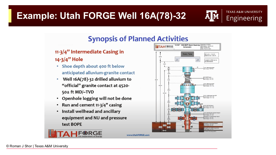
Fig. 268 Operational program detail from the FORGE DWOP: the intermediate casing plan (shoe ~400 ft below the alluvium-granite contact) and the 13⅝-in 10M BOP stack head-up schematic — the level of specificity a DWOP documents before the rig arrives.#
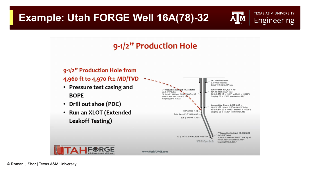
Fig. 269 The production hole program: pressure test casing and BOPE, drill out the shoe, and run an extended leak-off test (XLOT) before drilling ahead — stress characterization built directly into the drilling sequence.#
Schedule: The days vs. depth plot for this well showed approximately two weeks of surface preparation and rig-up, one day to drill and cement the surface hole, several days for intermediate section drilling and cementing, then roughly two weeks in the production hole. The total funded window was up to 100 days.
This kind of schedule is invaluable for a well with many third-party stakeholders. The geologist wanting core needs to be on site during the coring run. The micro-seismic team needs to be listening during fracturing. The stress-test team needs the well to be configured a specific way before their test. Without the schedule, these groups cannot coordinate.
22.7 Well Naming Conventions#
A brief note on well names, since they appear throughout DWOPs and in any field documentation. Well names encode a surprising amount of information.
In the United States, wells on public or state land are often named with a combination of:
Operator/lease prefix: “University” in Texas often refers to land owned by the University of Texas System, which holds large tracts from the original land-grant era. “FORGE” or “Forge” identifies the DOE test site.
Location identifier: A section/township/range system (in the Public Land Survey System) or a GPS-derived code may form part of the name. In Alberta, Canada, lease blocks are numbered sequentially from south to north, so the number encodes geographic position.
Sequential designator: A letter or number indicating which well this is in the series (16A, 16B, etc.).
University wells in Texas, for example, are wells drilled on land held by the University of Texas Permanent University Fund, including notably areas in the Permian Basin, and a portion of royalties from those wells have funded university operations for over a century. Texas A&M’s RELLIS Campus in Bryan/College Station has active producing wells and water wells that are visible from the road.
22.8 Key Terms#
Operator: The company holding the mineral rights and financial responsibility for the well. Owns the liability for lost downhole tools and wellbore incidents unless negligence by another party is proven.
Drilling contractor: The company supplying the drilling rig, crew, and related mechanical systems. Does not supply drilling fluid or most downhole tools.
Service company: A contractor supplying a specialized product or service (mud, bits, directional tools, cementing, logging). Downhole tools are leased; the contractor retains ownership and must have tools returned.
Daily drilling report (DDR): A formal daily record of all drilling operations, parameters, and decisions. The primary legal and technical record of what occurred during a well.
Company man: The operator’s on-site representative. Holds ultimate authority over drilling decisions at the rig.
DWOP (Drill Well on Paper): A structured pre-drill planning meeting in which all parties review the well plan in detail to align objectives, coordinate schedules, and identify risks.
Days vs. depth plot: A schedule chart with time on the horizontal axis and depth on the vertical axis. Diagonal sections represent drilling; flat sections (flat time) represent non-drilling operations.
Flat time: Time spent on operations that do not advance the bit: casing, cementing, testing, logging, waiting on services or equipment.
Anti-collision analysis: An engineering assessment of the planned wellbore trajectory relative to existing nearby wellbores, to ensure the new well will not intersect an existing one.
Data puck: An informal term for a ruggedized downhole sensor package (typically a vibration/IMU logger) run near the bit to record drilling dynamics data.
Pipe-light: A condition in MPD operations where surface back pressure increases buoyancy on the drill string to the point where the string weight indicated at surface approaches zero or goes negative. The string could be ejected upward by the wellbore pressure.
22.9 Practice Problems#
Problem 22.1: Responsibility for a Lost Tool
Problem: A service company is running a directional measurement-while-drilling (MWD) tool in a challenging salt section on an operator’s well. The operator’s company man authorizes the drilling contractor to increase the WOB (weight on bit) to improve ROP. During the next stand, the string gets stuck in a salt wash-out, and the MWD tool is lost below a fish. The service company bills the operator $400,000 for the lost tool. The drilling contractor argues that they were following the company man’s instructions. The service company argues that the MWD tool housing was not rated for the WOB used.
Who holds liability in each of the following scenarios? Explain your reasoning.
a) The service company’s tool spec sheet, submitted before the job, showed a maximum WOB rating of 50,000 lbs. The authorized WOB was 70,000 lbs.
b) The WOB was within tool specs, but the salt section was known to be prone to wash-outs (documented in offset well DDRs) and was not flagged in the DWOP.
c) The WOB was within specs and the wash-out risk was documented in the DWOP, and the driller was instructed to watch for over-pull.
Solution
a) Liability falls primarily on the operator. The company man authorized a WOB that exceeded the service company’s stated tool limit. The service company submitted their specifications in advance. The operator’s representative knowingly operated outside those specifications; the tool failure is a foreseeable consequence. The drilling contractor followed instructions from the company man, which generally protects them unless they had independent reason to refuse (and were not drilling out of specification for their own rig components).
b) Liability is shared, with significant exposure for the operator. The wash-out risk was a known hazard documented in offset DDRs. If it was not in the DWOP, the drilling team was not formally informed. The operator’s engineering team has a duty to compile and communicate relevant hazard information before drilling. The service company may have some responsibility if they were aware of offset well problems and did not raise the concern at the DWOP.
c) This scenario distributes liability most broadly. The risk was documented and communicated — the DWOP did its job. The driller was instructed to watch for over-pull, so they had the information needed to recognize a developing problem. If the driller ignored early indicators of sticking, liability may shift toward the drilling contractor. If the sticking was sudden and gave no warning, and the operation was being conducted within all specified limits, the operator’s liability for the tool replacement is clearest — they own the wellbore and the outcome — but their exposure to claims of negligence is lower.
Problem 22.2: Reading a Days vs. Depth Plot
Problem: A days vs. depth plot for a well shows the following features:
Days 0–3: No change in depth; depth remains at 0 ft
Days 3–4: Depth increases from 0 to 1,200 ft (surface hole)
Days 4–6: Depth holds at 1,200 ft
Days 6–9: Depth increases from 1,200 to 8,500 ft (intermediate hole)
Days 9–12: Depth holds at 8,500 ft
Days 12–25: Depth increases from 8,500 to 14,200 ft (production hole)
Days 25–28: Depth holds at 14,200 ft (total depth operations)
a) What is the total planned well time?
b) How many days were spent drilling vs. non-drilling operations?
c) If you are a geologist interested in being present for logging operations (typically run just before the final casing string), which days should you plan to be on site?
d) If the well actually took 35 days to reach total depth (with the extra 7 days added to the intermediate hole section due to a washed-out bit), sketch how the actual days vs. depth plot would differ from the planned plot in the intermediate section only.
Solution
a) Total planned well time: 28 days.
b)
Drilling days:
Surface hole: Days 3–4 = 1 day
Intermediate hole: Days 6–9 = 3 days
Production hole: Days 12–25 = 13 days
Total drilling: 17 days
Non-drilling (flat time):
Rig-up/surface prep: Days 0–3 = 3 days
After surface hole (casing/cementing): Days 4–6 = 2 days
After intermediate hole: Days 9–12 = 3 days
Final operations at TD: Days 25–28 = 3 days
Total flat time: 11 days
Flat time is 39% of total planned well time — a significant portion, typical for an onshore well.
c) Logging is typically run after reaching total depth of the production section, just before running the final casing string. In this planned schedule, that corresponds to Days 25–28 (the flat section after reaching TD at 14,200 ft). You should plan to arrive by Day 25 and be available through Day 28 (or whenever casing is run).
d) On the actual plot, the intermediate section would deviate to the right of the planned line partway through. Instead of reaching 8,500 ft by Day 9, the line continues diagonally (but possibly more slowly if tripping was involved) and reaches 8,500 ft around Day 16. Everything after that shifts 7 days to the right. The production hole section, final flat time, and total depth operations all occur 7 days later than planned, and total well time is 35 days rather than 28.
Problem 22.3: DWOP Gap Analysis
Problem: A drilling team is planning a horizontal well in a tight gas reservoir. They hold a DWOP and walk through their planned operations. After the meeting, the team reviews their DWOP document. Identify what is missing or potentially problematic in each of the following scenarios:
a) The casing program calls for 5½” production casing to be run to 12,000 ft MD, but the DWOP operational program does not mention a casing tally or a rig-up plan for the cement unit.
b) The well is planned to be drilled with a high-performance water-based mud through a known Haynesville shale section. The DWOP geology section mentions that the shale is reactive, but the mud section only specifies a 12.5 ppg mud weight with no additives.
c) The directional drilling section shows a planned DLS of 8°/100ft through the build section, but the drill string design section lists a mud motor with a maximum DLS rating of 6°/100ft.
Solution
a) Missing operational detail: The DWOP should specify when the cement unit needs to be on site, how long rig-up takes, and who calls the cement company to mobilize. Without this, the cement unit may arrive late (adding flat time) or the drilling contractor may be waiting for the cementer without knowing when they are expected. The casing tally — a measured list of every joint of casing with its OD, ID, and thread type — must be verified before casing is run. Its absence from the operational program means it could be overlooked until the last minute.
b) The reactive shale section requires inhibition additives in the drilling fluid, not just mud weight. Haynesville shale is known to be water-sensitive (hydration swelling) and to require a high-activity brine or a KCl-polymer system, or ideally an oil-based mud, to maintain wellbore stability. Specifying 12.5 ppg with no additives is incomplete and potentially dangerous — the hole may wash out or become unstable while drilling through this section. The DWOP should specify the mud system type, the potassium chloride concentration (if WBM), or the justification for accepting WBM rather than OBM in this formation.
c) This is a design conflict: the planned well path requires 8°/100ft DLS, but the selected mud motor can only steer at up to 6°/100ft. Either the directional plan must be revised to a shallower build rate, or a more capable motor (or a rotary steerable system) must be selected. Running a tool outside its design limits increases the risk of failure, potentially losing the motor in the hole. This kind of conflict is exactly what the DWOP is designed to catch before the rig is on location.
Problem 22.4: DWOP Structure
Problem: You are a junior drilling engineer tasked with preparing the outline for a DWOP for a new geothermal exploration well in a frontier area (no offset wells). The well will be vertical to 9,000 ft, targeting a granitic basement formation at a temperature of ~290°F. The operator intends to test for permeability and run a short flow test. List the six DWOP components and describe, in two to three sentences each, what specific information you would prioritize in each section given the frontier and high-temperature nature of this well.
Solution
1. Program Objectives: State that the primary objective is exploration — to characterize a potential EGS resource for future development. Define the technical success criteria (e.g., maximum temperature achieved, permeability from flow test, core quality). Identify secondary objectives such as tool testing or formation evaluation data collection for future well planning.
2. Site and Geological Information: Because no offset wells exist, present all available geological information: surface outcrop mapping, seismic reflection profiles if available, regional stress data from published literature, and any nearby well data from other operators. Be explicit about uncertainty — the pore pressure and fracture gradient profiles are estimated, not confirmed — and plan for a wider-than-normal drilling window margin to account for that uncertainty.
3. Well Design Summary: Document the casing program conservatively (possibly one more string than a development well would require, given the uncertain formation pressures). The BHA and drilling fluid program must explicitly account for the 290°F temperature — confirm all selected tools are rated above this temperature, and specify a fluid system compatible with high temperature (some polymer additives degrade above 250°F). Document the flow test completion design.
4. Operational Program: Walk through each section and call out the operations unique to this well: the formation integrity tests at each casing shoe (critical given uncertain FG), the temperature-logging run to confirm temperature profile before committing to final hole section operations, and the flow test procedure including all safety and well control aspects for a geothermal flow event (which can produce steam).
5. Days vs. Depth Plot: Build the schedule with extra contingency in the production hole section given the hard granite and high temperature. Flag that the schedule includes time for temperature stabilization runs and that the flow test duration is variable depending on results. Identify key milestones that require third parties on site (logging, flow test team) and mark them clearly.
6. Special Operations and Risk Identification: Highlight the two primary risks for this well: (1) downhole tool failure from temperature exceedance — plan for staged tool installation with temperature monitoring before exposing the most sensitive equipment to maximum depth, and have contingency BHA configurations that use more temperature-tolerant tools; (2) geothermal well control — if the well flows on its own (artesian flow or steam flash), standard oil and gas well control procedures may not be fully adequate, and the DWOP should include a geothermal-specific well control response plan with the appropriate BOP configuration.